Dan Toma - YO3GGX - yo3ggx@gmail.com Please do not to give negative feedback in the Google Play Store before contacting me by e-mail to clarify any issues with the application. I promise to answer you ASAP. PocketRxTx is available as a free application (Ads based) or as a “Pro” version, with no Ads and some extra features. Please install the free version first to check it if is useful for you and only if so, consider buying the Pro version.
IntroductionPocketRxTx is an Android only application used to remotely control different Amateur Radio receivers or transceivers. You can connect through the Internet to a WebSDR server or via a Bluetooth, USB/Serial or network connection to your own Amateur Radio transceiver.
The current version of the application has the following general features:
Works on any Android device, including smartphones, tablets and Google TV, with a minimum screen resolution of 800x480 pixels and running Android version 4.0.4 or higher.
Works in both portrait and landscape modes.
Audio and CAT commands are transferred in the background
Tuning is possible;
through the rotary knob
by directly entering the frequency from a numeric keypad (in MHz)
Or by using Up/Down buttons to change the frequency with a preset step value for (+ and -), which can be dependent upon the selected band;
16 pre-set channels can store all currently set parameters in 16 memories (frequency, name, description, band, mode, etc.);
The ON/OFF button connects or disconnects the application from the remote server or locally connected transceiver;
Bands may be selected from the list of valid ones for the transceiver model.
Operating mode (AM/ LSB/USB/CW/ etc.) may be selected from the application
The Signal strength in receive and SWR in transmit are displayed both in graphical and text mode
You may set the font size according to your preference
A FN key extends the number of keys available to perform CAT actions on the transceiver.
A UTC clock is included in the interface.
Call logging available, including QRZ database query support
Selectable tuning band stops by IARU region.
User configurable beep/vibration on pressing of buttons
Specific functions direct CAT mode (i.e. not WEBSDR):
Can connect to the transceiver over Bluetooth, USB/Serial or Network;
USB/Serial multi-port interface support. With PTT over CAT, RTS or DTR (user selectable), selectable comms port (e.g. Yaesu FT-991 USB or SCU-17 interface)
Network connection with secure authentication if required;
When using a network connection Bi-directional audio support is available without the need for external applications such as Skype;
All on the Android device stored radio configs are associated with specific Bluetooth/USB/Network profiles, to allow operation of different radios without having to re-enter the configuration data each time you switch between them;
Radio model support is controlled through a textmode configuration file and can be edited by the user. Support for the following transceivers is already available in the central repository, accessible from the application GUI:
Elecraft: K3, KX3;
Icom: IC-703, IC-718, IC-746, IC-746Pro, IC-7000, IC-7100, ICR-7000, ICR-71E, IC-7200, IC-7300, IC-7400, IC-9100;
Kachina: 505DSP;
Kenwood: TH-F6/F7, TS-480, TS-480SAT, TS480hx, TS-570, TS-590, TS-870, TS-2000;
Mini: SW-2012, SW-2012C.
TEN-TEC: Orion;
XIEGU X108G
Yaesu: FT-100, FT-817, FT-847, FT-857, FT-891, FT-897, FT-450, FT-950, FT-991, FT-1000MP, FTDX-3000, FTDX-5000;
The textmode file defines how the following functions of the transceiver are controlled via CAT commands (the file is extensible and customizable by the user): Mode, Band, VFO, Output Power, PTT, ATU (ON/OFF), Tune, AGC, NR, NB, IPO, etc.
The user can define synchronization (feedback) between the application and the radio for several CAT controllable functions.
To edit the textmode configuration file Import/export between the Android device and a computer is provided through the jAReC network server program which may also be used for configuration backup purposes.
Specific functions in SDR Receiver mode:
PocketRxTx can connect to any one in a list of WebSDR servers. New servers can be added to the list in the future without requiring any application update;
Receive mode (AM/USB/LSB/CW/FM), IF bandwidth (Normal/Narrow/Wide), and Band/frequency can be selected through the application;
The application has a waterfall/spectrum display with a zoom of up to 64x (for RTLSDR based servers);
By using the user’s and the WebSDR server’s geographic coordinates the distance between them is displayed (more details are available if the Location Service in the Android device is activated).
The application contains a Mute button.
For SWLs call logging support with QRZ database query is available but only in the Pro version.
The current version of the application may have limitations:
A number of tests were performed however without having access to every possible Android device and every rig in the supported hardware list, testing cannot be comprehensive. This means that the application may have bugs, or may crash for apparently no reason. With your help as users, issues can be solved one by one and new features added. This is the model used so far to advance the development of the product and it is hoped that this co-working method can continue.
Note at present over the network connection encryption is used only for the initial authentication (login) to the server, after that all the traffic is unencrypted, for both CAT and audio. If security is required, the use of a VPN or tunneling protocol is recommended.
WARNING!!!
Use this application at your own risk. When using a network connection, it is possible that your PC may be accessible from the Internet. It is your responsibility to address this risk if you consider it to be an issue. One possible approach may be to use some kind of VPN (e.g. PPTP). The application only provides secure login authentication, no data encryption. A full encryption option is planned to be added in the future. If you are not comfortable with this situation and you are not able to use any kind of VPN, then only use the network link from the App over your own internal LAN.
This application does not send any “dangerous” data to the transceiver however as the protocol used by Yaesu for FT-8x7 CAT control does not use any error correction mechanism, it is possible (in some unlikely situations) that unexpected results may occur such as a software crash on the transceiver (requiring to power cycle to rectify it). In a worst-case scenario a complete wipe of all EEPROM data, including configuration, software calibration/alignment and memories is theoretically possible. As all CAT commands used by PocketRxTx are user customizable by just editing a text file, extra caution must be exercised when changing the radio configuration textmode file.
In the case of Yaesu FT8x7 equipment it is highly recommended to save your transceiver settings using a program such as “FT 817 Commander” (you can use Google search to find it) before starting to use this application. As a minimum save all “soft calibration” settings, plus any other information stored in your radio before using this application.
I cannot be held responsible for any damage caused to your Android device, your transceiver or your PC… You have been warned!
You can install the application directly from the Google Play Store (search for “PocketRxTx”).
NOTE: If you are running the application on Android 6.0 and above, no special permissions are generally required to run it. Only if specific permission is required to be provided in order to access some application features, will you be asked to grant permission. If you deny this permission, just that feature will not be available. On Android versions up to and including version 5.x, permissions required by all the application’s features will be requested during the application installation. From version 3.0 of PocketRxTx, this application does not require access to the media files area anymore.
After you install the application, a new icon similar to the one below will be available:
Press the icon to launch the PocketRxTx application.
During the first start of the application or after doing an application reset (see later), you will be prompted to enter your callsign and choose the default start mode: Direct CAT (control of your rig) or WebSDR (control of web-based receivers).
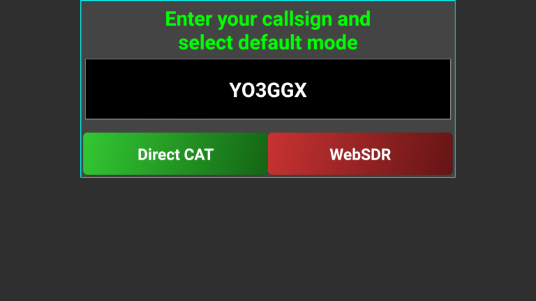
The callsign will be used for the call log if you enable it and to identify you when you access a WebSDR.
If you select WebSDR mode the first time you run PocketRxTx (or after a factory reset), the first WebSDR server which answers a request from the application is selected by default. The startup page will appear (in Landscape or Portrait mode).
NOTE: In Android’s Notification bar, a small icon will be present once the application is started, even if is running in the background. If you press the related notification text, you will bring the application back to the screen. Note: this is only the case if NOTIFICATION is activated (for how to enable/disable NOTIFICATION see later in this document).
![]()
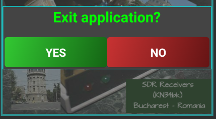
To exit the application at any time,
click on the
![]() icon. You will get the following message prompt.
icon. You will get the following message prompt.
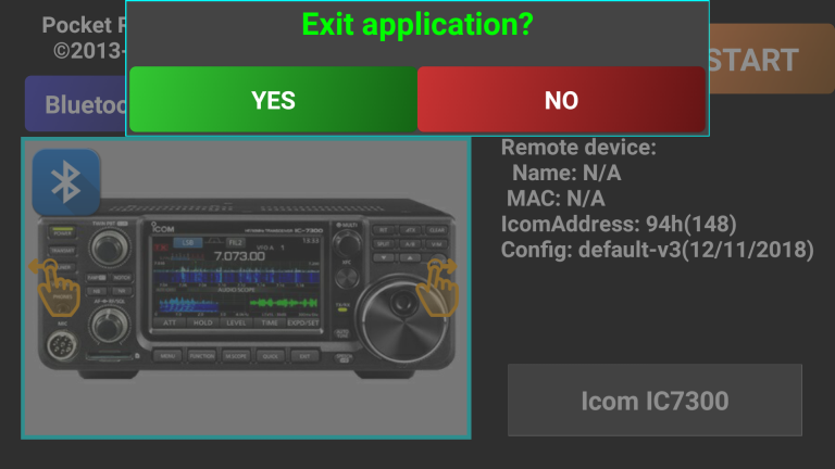
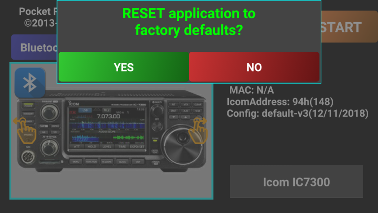
Click on YES if you want to exit or on NO to return to the PocketRxTx screen.
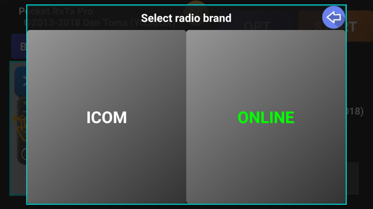
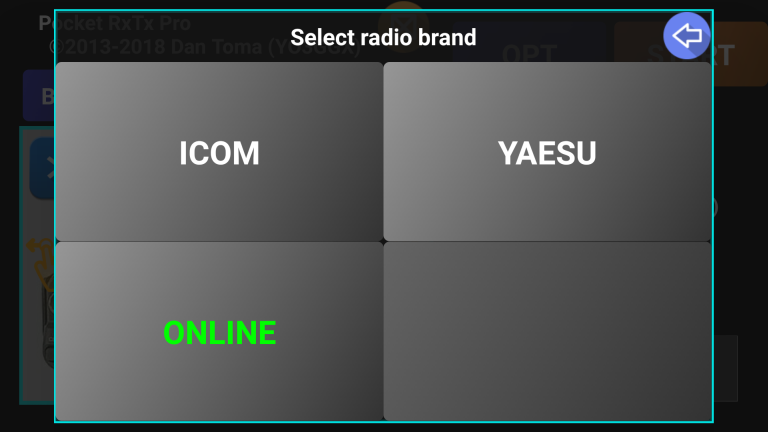
If you select Direct CAT mode at first run (or after a factory reset), a wizard will start that will help you configure the app for this mode. You will be first prompted to select transceiver brand. As you can see, the names are displayed in green. This indicates that the data is coming from the online central repository via the Internet.
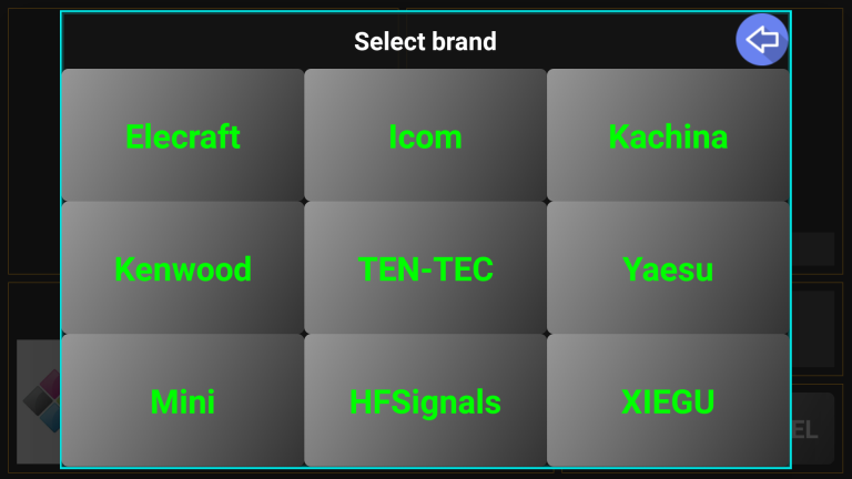
NOTE: Throughout the application configuration, the text on the buttons in selection panels can have different colors. In this case, green means that this is an online selection (files will be loaded from the central server).
Select the desired brand by clicking on the desired brand name. You will then be prompted to select a model from that brand. Here we take Icom as an example.
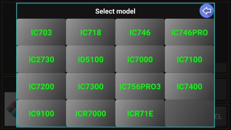
Click on the desired radio model. Let’s select IC7300. If multiple configuration files are available for that specific radio model, you will be prompted to select which one you wish to use. In this particular case we have 2 default versions: one for PocketRxTx v2, the other one for PocketRxTx v3.
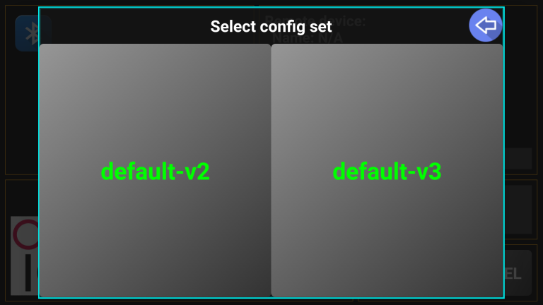
Any user is welcome to publish his own configuration in the central repository, in order to share it with other users of the same transceiver. You just have to send your radio configuration file to me by e-mail.
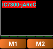
Here we clicked on the desired configuration version - 3. Some info about the selected radio is displayed: version, author, date, brand logo. If you want to select a different radio, just click on the radio brand/model box.
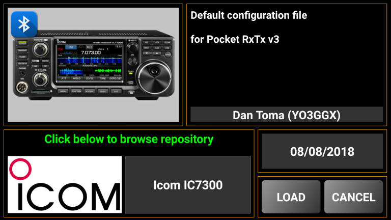
As this is the configuration we want, we click on LOAD to save the selected configuration file locally on the Android device. You will be prompted for a confirmation.

Once we click OK the configuration file will be available locally and the next time you start PocketRxTx this model will be selected.
In the next step in the initial configuration process you will be asked which connection mode you will be using to access your radio. You can connect over Bluetooth (CAT only), USB/Serial cable (CAT only) or over the network (CAT and Audio).
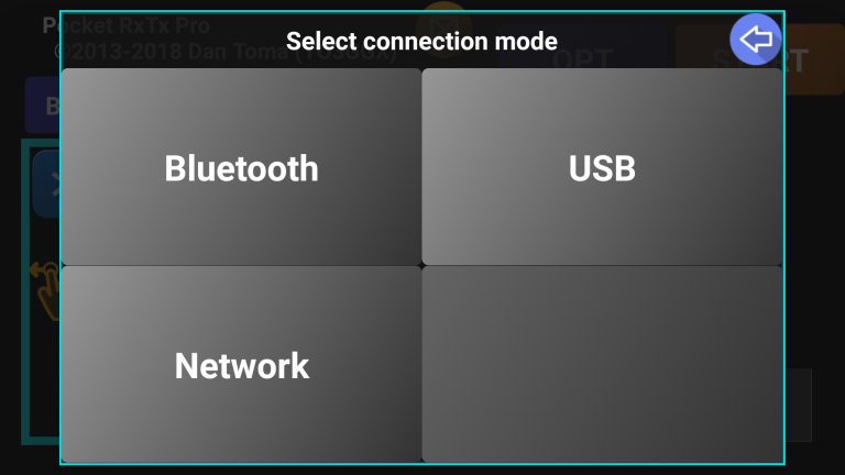
NOTE: To be able to use a USB cable connection for control, the Android device has to support “On the Go” or OTG mode. This changes the Android phone or tablet into being the “host”, the same role that a PC or laptop has and not the slave (dumb device) that it normally operates as. The Android device has to be able to send the CAT commands. If your Android device has an older version of Android or one that does not have OTG support, you should look at the network or Bluetooth connection options. To tell the Android device to switch into OTG mode an OTG USB cable or OTG adapter is needed (these are cheap items, but without it the Android device will not be able to communicate over the USB cable with the radio).
When you click on the desired connection mode, the setup page for that mode is opened, as described below.
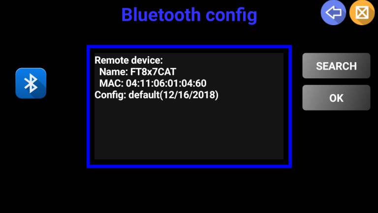
When you click on “Bluetooth”, the following configuration page will be displayed.
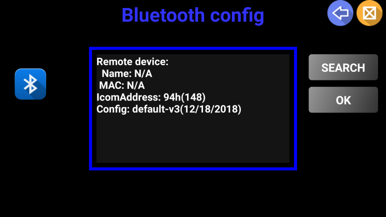
Check that you Bluetooth CAT interface is switched on and in pairing mode. Click on SEARCH to start searching for Bluetooth devices.
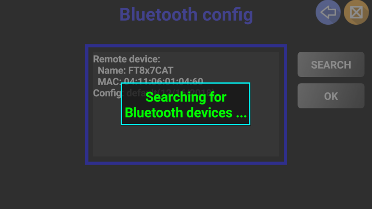
After a few seconds, a list of discovered Bluetooth devices will be displayed.
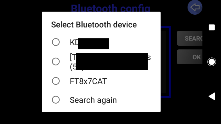
Select your Bluetooth (BT) CAT interface from the list. Some information such as name and MAC address will be displayed.
NOTE: If initially your device is not discovered, you can click on “Search again” to repeat the search, if perhaps the BT device was not turned on in time.
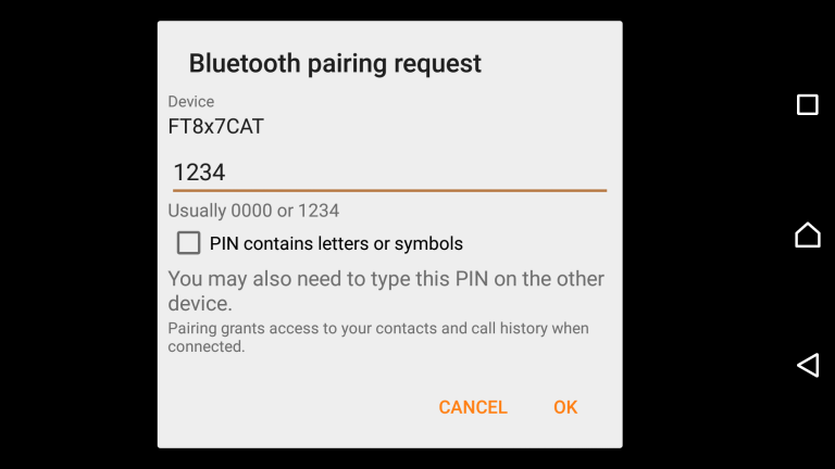
If the BT CAT device was not paired with Android previously Android will ask you to authorize pairing now.
If you click on the “USB” connectivity option, the following page will be displayed if the connection is not in place.
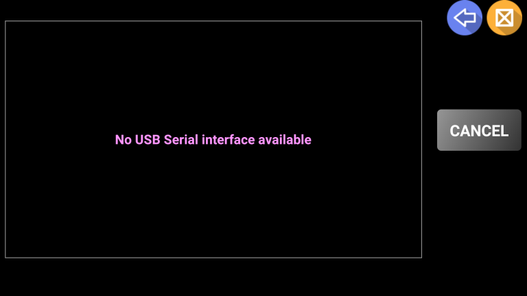
You may connect your USB “OTG” cable between the Android device and your rig’s USB port or your Computer to rig digital interface (if the device is in the list of supported USB serial port chipsets).
You will be asked by Android to allow this application (pRxTx) access to the USB device and whether PocketRxTx should be the default App to load when Android sees this interface in the future.
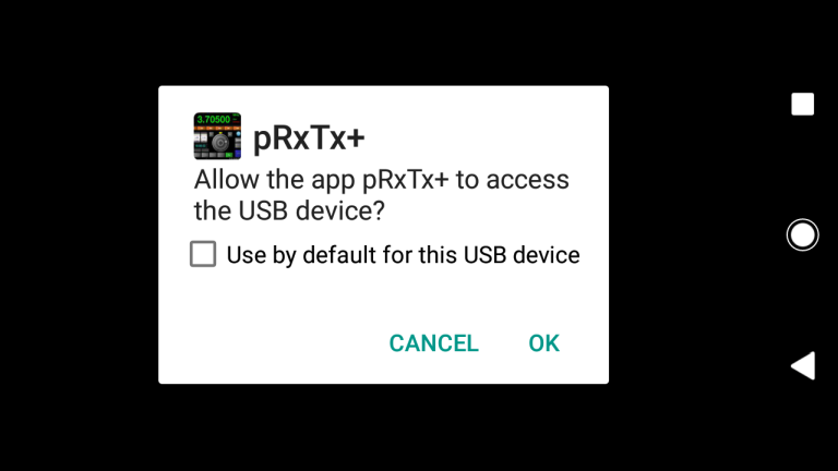
Check “Use by default for this USB device” and click OK. The USB setup page will now appear to ask for details about the connected interface. Taking as an example the Yaesu SCU-17 digital modes interface, you will see the following.
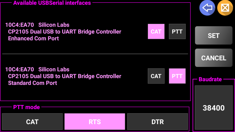
Select the desired interface to be used for CAT and for PTT. Depending upon the interface hardware or the USB Chipset in the rig, there may be one or two interfaces displayed at this point. Your selected options will be displayed in magenta. Click on the desired mode to send PTT commands: RTS or DTS signals from the selected serial port, or CAT if you want PTT to be send as a CAT command. In the example above, PTT is sent through the RTS line over the second serial port.
NOTE: Some transceivers require PTT to be controlled over a pin on an accessory socket on the back of the radio. PocketRxTx can only “talk” to serial communications connections that it sees through the USB connector so Interfacing between the radio and the Android device running PocketRxTx will need to take this into account. Several different approaches are taken on different radios to provide computer control and you will need to refer to your radios documentation to understand what is required to control the radio from a USB computer interface (as is used by PocketRxTx).
Click on the Baudrate button to tell PocketRxTx what speed the USB serial communications channel is defined as in the radio (direct USB connection) or the interfacing hardware (as used for radios without a USB port on them).
Once selected the speed is displayed in green.
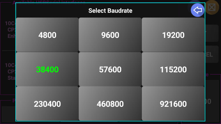
Once the Baudrate is set, you are returned to the USB setup page, if you don’t wish to change your choices click on SET to save the values in a local radio profile file.
In the current version of the application USB CAT interfaces based on the following USB/Serial chips are supported:
FTDI FT230XS UART VID: 0x0403 PID: 0x6015
FTDI FT232R UART VID: 0x0403 PID: 0x6001
RT Systems CT29B VID: 0x2100 PID: 0x9E54
RT Systems USB-62 VID: 0x2100 PID: 0x9E56
Arduino VID: 0x2341 PID: xxxxxx
Teensyduino VID: 0x16C0 PID: 0x0483
Atmel VID: 0x03eb PID: xxxxxx
CP210x UART Bridge VID: 0x10C4 PID: 0xEA60
Prolific PL2303 VID: 0x067b PID: 0x2303
CH340 VID: 0x1A86 PID: 0x7523
STMicroelectronics STM32 VID: 0x0483 PID: 0x5740
To connect over the network, prior to selecting this option in PocketRxTx, you need to have the jAReC program running on a computer which is connected to your transceiver via a USB cable. jAReC is a small, portable java application that can run on Windows, Linux, Mac, or even a Raspberry Pi. For the jAReC (full GUI) user guide click here. There is a command line version of jAReC called jarecmini. For the jarecmini user guide click here. The jAReC and jarecmini programs are available for free download on my web page (check the corresponding user guide for more details).
When you click on “Network”, the following configuration page will be displayed.
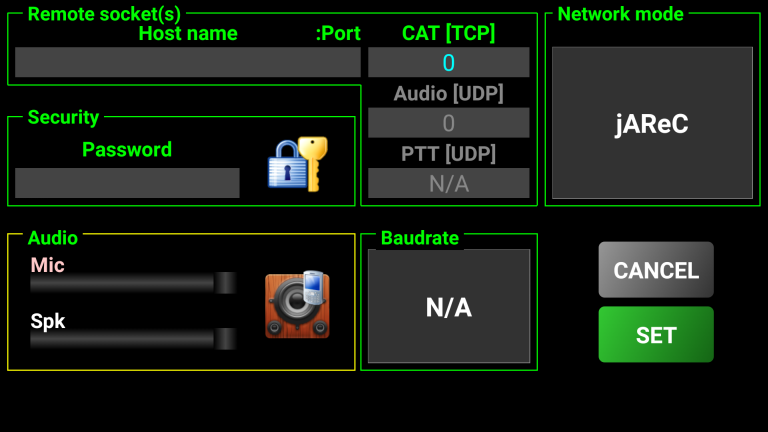
Here is an example of a completed configuration screen:
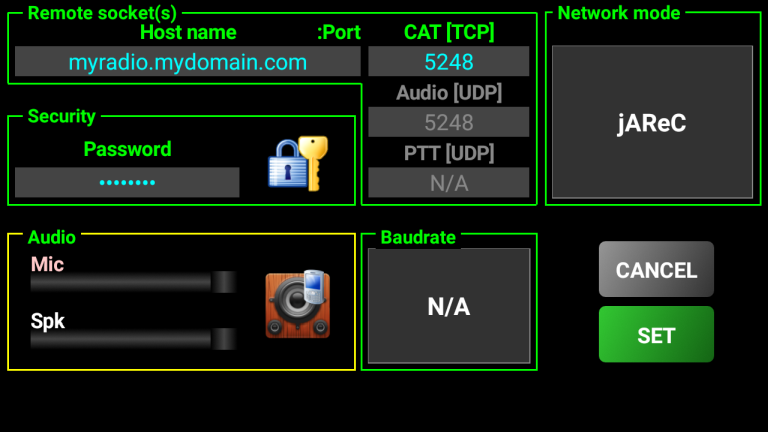
Explanation of the different network configuration fields:
Host name – This is the fully qualified domain name of your router (if connected over the Internet) or the IP address on your local LAN of the PC/Mac/Linux PC/Raspberry PI running the jAReC server application or the Rigexpert WTI-1 interface box. If you will connect via the Internet and your server is behind a router, (which it will normally be), enter the external hostname or IP address of the router (the address it has as a device on the Internet). If you are not allocated a “static IP address” or “static hostname” by your ISP, you should look at implementing a dynamic DNS link which will ensure that if your router changes it’s address on the Internet – the “Dynamic Hostname” automatically goes to the new IP address. In the router you must configure port forwarding to the computer where jAReC or jarecmini runs. You must configure port forwarding for both UDP (used for audio) and TCP (used for CAT) on the port number you enter in the next field. It is simplest if you configure a static IP address within your local LAN for the computer running jAReC / jarecmini and this is the IP address that you tell your router to send all data traffic on the port number you chose to.
CAT port – TCP port configured in jAReC for CAT. The same port number is used for both audio and CAT. You must enter only the CAT port; the audio port is set automatically to the same port number only using UDP.
Audio port – this is for jAReC mode the same one as for CAT, but on UDP (it is auto filled from what you enter in the CAT Port field.
Network Mode - 3 network modes are available:
jAReC (used to talk to either jAReC or jarecmini with both CAT and audio channels)
RigExpert WTI-1 used to talk to the RigExpert WTI-1 interface box (currently only CAT (rig control) is supported no audio transfer)
dAReC used to talk to a future Android version of jAReC, so that an Android phone can serve in place of the PC – dAReC is still under development.
Security - Press the padlock icon to toggle login authentication ON/OFF. You can enter the password only when authentication is activated. Password is mandatory if authentication is activated. For security from access by others the use of the authentication option is recommended.
Audio - Press the round blue speaker to toggle audio ON/OFF. In RigExpert WTI-1 mode, you will be able to adjust the audio level using the sliders when the audio option is activated (not yet available). If audio is activated in jAReC mode, a thin line meter will be displayed under the frequency display in the main app window.
![]()
This meter will show you, when connected to jAReC, the mic level from your Android device.
To learn how to configure jAReC, for audio click here (for jAReC) or here (for jarecmini).
You can deactivate authentication and/or audio by clicking on the respective icons. When deactivated, the icons will change as shown in the following pictures.
![]()
![]()
When you are happy all parameters on the network configuration panel are correct click on SET and you will be returned to the start page.
If you have multiple transceivers that you wish to control, you can have local configuration files for each of them.
NOTE: You can download as many radio configuration files you need from the central repository. You could load all available, but you will only be able to maintain one configuration for each brand/model.
To load another radio configuration or to reload an updated version of a configuration for the same radio, touch the grey box which is displaying the currently loaded configuration file name.
Here is an example of how to add a new radio – in this example the Yaesu FT-817 to an ICOM model that we already have installed.
After touching on the brand/model grey box you are prompted to select between a locally available configuration or one available from the online central repository.
All locally stored radio configs are displayed in white. Click ONLINE to load a new config from the central repository.
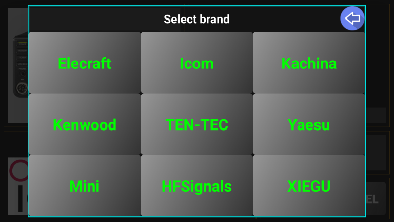
Click on the desired brand (in our example Yaesu) and we see a new panel:
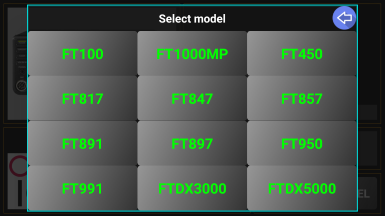
Click on the desired radio model (FT-817) and if there are multiple possible configurations, these will be displayed for you to choose between.
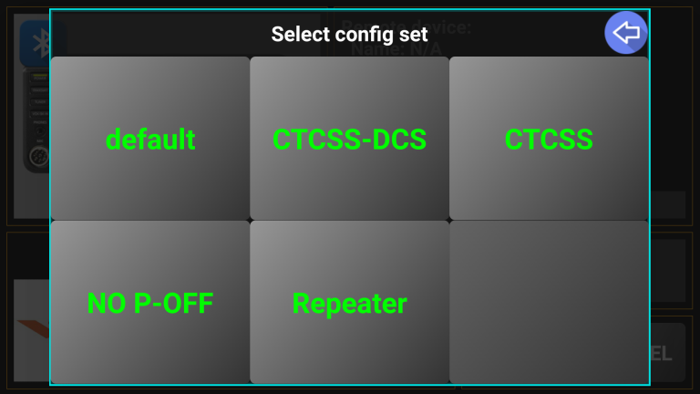
Click on the desired config version. (we chose “default”)
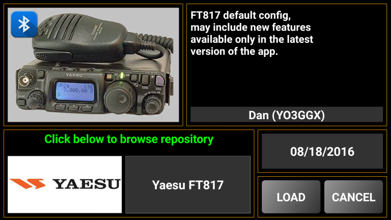
Click LOAD to save the new configuration file locally from the repository to your Android device.
If you click again on the current radio brand/model grey box (Yaesu FT817 in this case), you can see now radio configurations from two makes are now available locally (local configs are shown in white text).
You can now easily switch between the locally stored configs when you need to without the need to access the central repository. If for a specific make you have just a single radio config saved locally, you will no longer be prompted to select the radio model (it becomes the default).
NOTE: For each locally stored radio config, a dedicated profile is created. This profile contains connection settings, so when you switch to another locally stored radio, the associated profile is loaded at the same time. For example, you may connect to an ICOM rig via the network and to that Yaesu FT-817 over a direct USB cable. When you switch rigs in PocketRxTx you will also switch connection if needed.
The last used mode (i.e. WebSDR client or Direct CAT connection) is saved when you exit the application, so the next time you start the App, it will be in that mode.
Of course, you can switch between WebSDR client and Direct CAT mode when required and this is done from the startup page at any time simply by touching one of the two orange hands graphics.

To close the application at any
time, click on the CLOSE icon.
![]()
You will be asked if you want to exit application. Press YES to confirm.
This button is used to access more complex features. The structure is presented in the table below, depending on operation mode (WebSDR client or Direct CAT) the options are different. Click on any menu item for more information. See the previous page in this documentation to learn how to switch the mode between WebSDR and Direct CAT).
NOTE: Some of the features are not available in the free version. For the whole list of differences between Free and Pro version, click here.
|
LEVEL 1 |
LEVEL 2 |
|
LEVEL 1 |
LEVEL 2 |
MYCALLSIGN – you can enter or later edit your callsign, that normally is saved when you first run the application. This is used for several purposes:
Automatically fill your personal data from QRZ when you create a new call log entry (see here).
Display your connection name in a standard WebSDR web page.
Help to calculate the distance from your QTH to the WebSDR server you are connected to (in WebSDR client mode), or to your correspondent (in Direct CAT mode)
When you click on this button, you are prompted to enter the callsign.
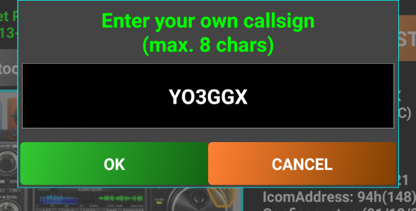
Click on OK after you check that the data was entered correctly, or cancel to return without saving the new callsign.
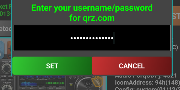
MYQRZ – Click on this button to enter your ‘qrz.com credentials. Data is stored only on your device.
Enter username and password in a single line, separated by ‘/’ character (‘mycallsign/mypassword’) and then click SET.
This step is required only if you want that callsign info to be automatically downloaded from the QRZ database (for you and for your correspondent).
E-MAIL - You can export locally stored call log file by e-mail by just clicking on this button.
NOTE: If no default e-mail application is defined on your device, you may be prompted to select the application you want to use to send the call log file.
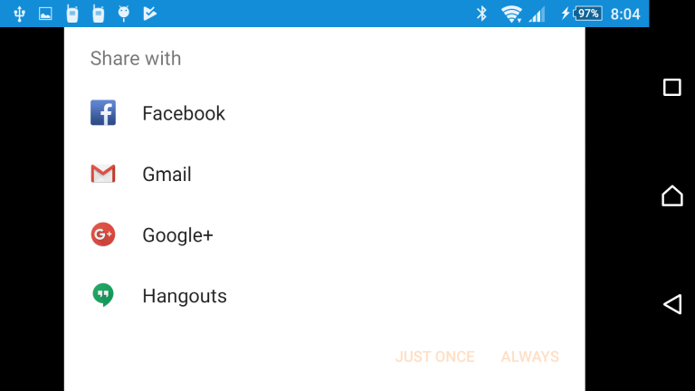
Select one of the e-mail applications (ex. Gmail) and then click on ALWAYS.
The e-mail application on your device will be automatically opened and some fields populated: ‘To:’ (your e-mail address if available in your own QRZ record), subject ‘Pocket RxTx ADIF Call Log logbookyyyyMMddhhmmss.adi’, message body ‘This is a Pocket RxTx ADIF Call Log created on mm/dd/yyyy hh:mm:ss’. The log file is automatically as text in the message body. You can later save that section in a file with the extension ‘.adi’ in order to use it in other applications.
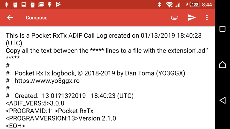
You can edit any e-mail field before clicking on send. When ready, click on send button from the e-mail application to send the e-mail to the specified address.
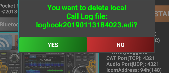
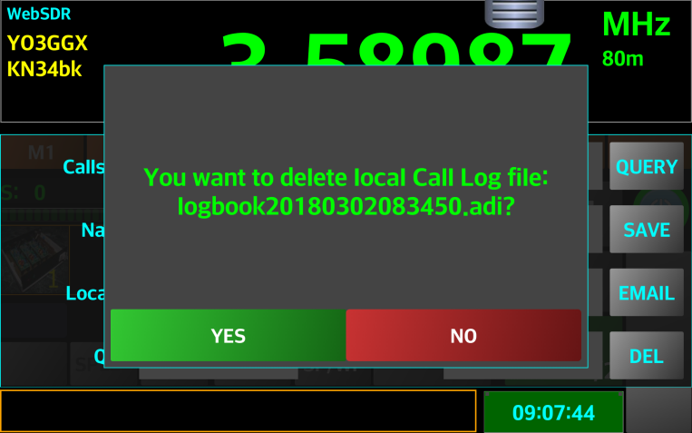
DELETE – click on this button to delete locally stored call log, if available. A short message will be displayed to confirm that the file was successfully deleted, or that the file does not exist (no local call log file available).
RELOAD – (WebSDR mode only) refreshes the list of active WebSDR servers that are available.
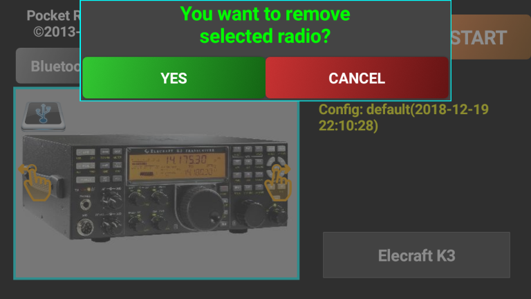
REMOVE – (Direct CAT mode only) removes the currently loaded local radio configuration file. You are prompted to confirm the removal.
BANDSTOP – set band limits based on IARU regions 1, 2 or 3 band plans.
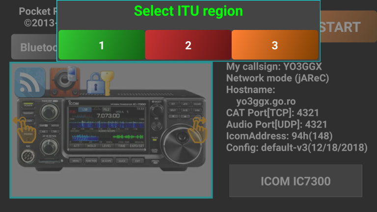
When a specific band plan is selected, tuning using the knob or +/- buttons is limited to the currently selected band. This can be useful to prevent the exit from the amateur bands. This button act as a toggle. First time you use it, you are prompted to select the ITU region you want the radio to lock on. A short message confirms your entry.
Next time you enter EXTRAS menu, the BANDSTOP button will be green, to show you that this feature is activated.
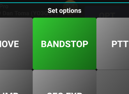
If you now click on BANDSTOP, this feature will be deactivated and a short message will confirm this.
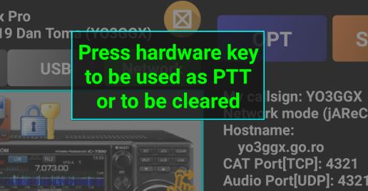
PTTKEY - (Direct CAT mode only) There is the ability to assign a physical key on the Android device to act the same as the graphical PTT button. This option allows you to select or clear the hard-key. Examples are volume-up, volume-down and on phones with one – the camera button. If you click on PTTKEY button, you will be prompted to press the hardware key you want to be assigned as a PTT key.
Let’s for example press the camera shutter button on a Sony Xperia ZL.
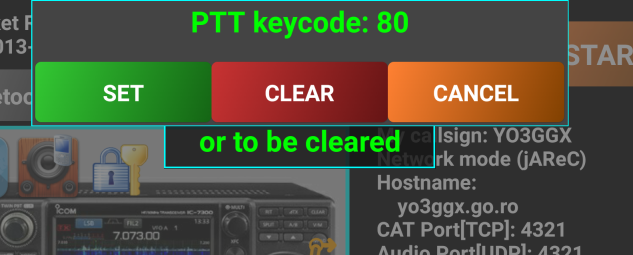
The code associated with that key is displayed. You have the option to click SET if you want to associate the key with the PTT button, CLEAR to clear a previous association or CANCEL to cancel the operation.
NOTE: Please be aware that if you associate a hardware key with PTT, the PTT button from the GUI will be disabled.
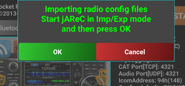
CFG IMP, CFG EXP – (Direst CAT only) – by using jAReC over the network in Cfg Imp/Exp mode, the radio configuration text file can be transferred to your PC, edited as required there and then sent back to the Android device.
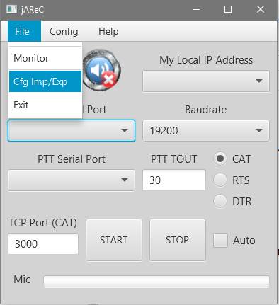
CFG EXP is used to transfer from the phone/tablet to the PC and CFG IMP to transfer the file back from the PC. To export the configuration from your PC, click on CFG EXP button. You will be prompted to start jAReC in Cfg Imp/Exp mode and then to click on OK.
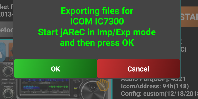
Then the following files (if exists) will be transferred from Pocket RxTx to the folder where jAReC application resides, in a subfolder named “configs”:
All locally available radio configuration files (*.radio)
All locally available radio picture files (*.jpg)
All locally available radio profile files (*.prf)
All locally available memories files (*.mem)
Call log file if available (*.adi)
debug.log file, containing debugging information. This is only available if debug mode was activated during current application section. Check here for more details about how debugging works.
If the subfolder does not exist, will be created at first export.
To import a set of configuration files from the PC, click on CFG IMP button. You will be prompted to start jAReC in Cfg Imp/Exp mode and then to click on OK.
The following files (if exists in the “configs” subfolder of jAReC) will be transferred from the PC to Pocket RxTx:
All radio configuration files (*.radio)
All radio picture files (*.jpg)
All radio profile files (*.prf)
All memories files (*.mem)
If the subfolder does not exist, no file will be imported. This feature can be very useful if you want to edit or backup your specific configuration.
These options are common to both WebSDR and Direct CAT modes.
ANIM - used to activate/deactivate interface animations. When selected the button background turns green.
NOTIF - used to activate/deactivate application notification. When notification is activated and the application is running (even running in the background), a small icon will be visible in the Android task bar.

ALWAYSON - used to disable automatic standby of your device. When active, the device will never go to sleep and the display will be always on. Please take into consideration that this will drain your battery much faster, so is better to use it only when the device is connected to an external power source. When this mode is activated, in the main radio screen, radio/connection name (in Direct CAT mode), or current mode (in WebSDR mode) label background goes red.
BEEP - used to enable/disable key beep. If activated, every time you click on a button, a short beep will be generated through the device’s speaker.
VIBRATE - used to enable/disable haptic feedback. If activated, every time you click on a button, you will feel a short vibration.
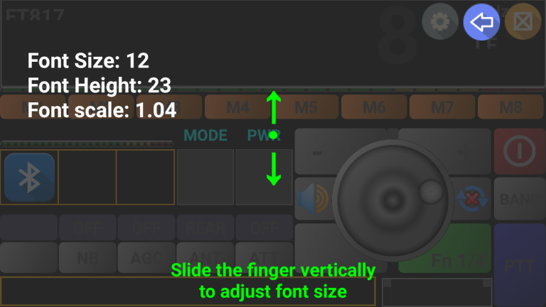
FNTSIZE – used to change the default font size used in the application. Under normal circumstances, the font size is automatically set by the application the first time it starts.
On some Android devices it is possible that application fonts may be too big or too small (based on the Android system settings) and hence need changing with this app. You may just wish to adapt the size to your own preferences. To change the font size, slide your finger vertically over the semi-transparent area (up to increase, down to decrease).
The new value for the font size will be displayed.
For better visibility select the
biggest font which does not generate overlapping. When set, click on
the BACK icon
![]() .
The new font size will be automatically saved in the application
configuration file. The next time you start the application, the new
font size will be used.
.
The new font size will be automatically saved in the application
configuration file. The next time you start the application, the new
font size will be used.
DEBUG – used to activate debug/logging mode, when requested by the programmer to assist with fault finding.
When activated, a debug file will be created (debug.log) in the app folder. This can help in some specific situations to troubleshoot issues. When debug mode is activated, the info box in the lower part of the radio screen will go green.
![]()
Logged data is first written into the info box. The debug log is always removed when you close the application. You must export it to a PC through jAReC, using the export function in order to save it, before closing the app. Export procedure is described here.
RESET – used to reset the application to factory default (which has the same effect as uninstall followed by a fresh install). When selecting this option, you will be prompted to confirm.
CONTENT - used to access the application online user guide.
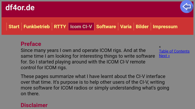
PROTOCOL (only in Direct CAT mode) - used to access CAT protocol documentation (if available for the selected radio) – this is an example for ICOM’s CI-V protocol:
To exit, click on the blue BACK icon.
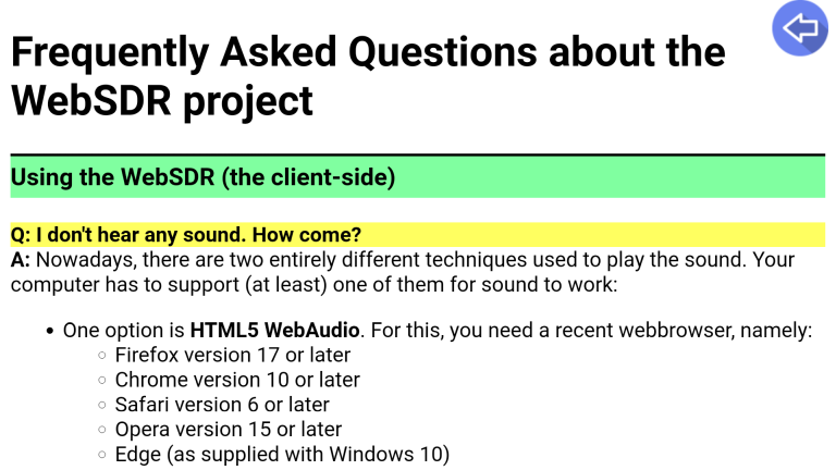
WebSDR FAQ (only in WebSDR mode) – as the title suggests, the option contains documented Frequently asked questions about the WebSDR project (the network of devices from which a receiver can be selected)
To exit, click on the blue BACK icon.
PROvsFREE - used to directly access the section in the user guide where the differences between Free and Pro version
ABOUT - used to display current application version.
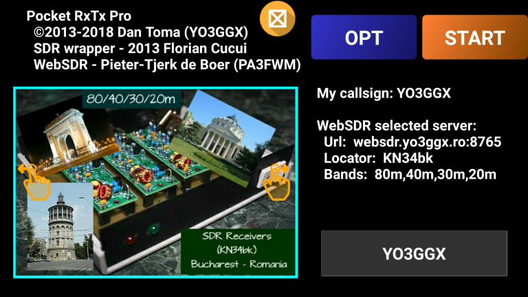
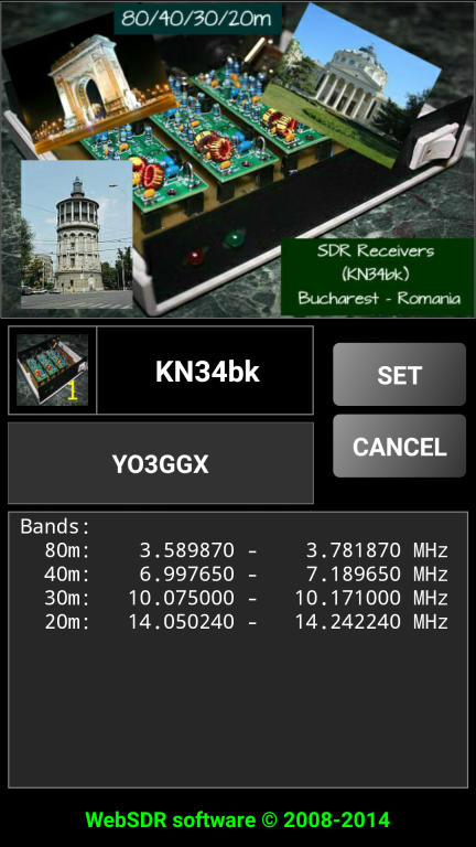
This is how the startup page looks in WebSDR client mode.
In the upper part of the screen is a text box containing the application version (Pro or Free) and some info about the contributors. The picture represents the selected WebSDR server and is provided by the server owner. In the gray text box is the callsign associated with the currently selected server. Also displayed is info about the WebSDR server:
Server URL
Server grid locator
Available bands
The blue OPT button is used to access application settings, depending on the mode (see here).
Click on the orange START button to enter main application screen.
Click on the server icon in the left part of the screen
![]() or on the setup icon in the upper right part of the screen
or on the setup icon in the upper right part of the screen
![]() to enter WebSDR setup page.
to enter WebSDR setup page.
NOTE: You can go directly to the WebSDR setup page from the startup page if you click on the
server callsign in
the grey box e.g.
![]() .
.
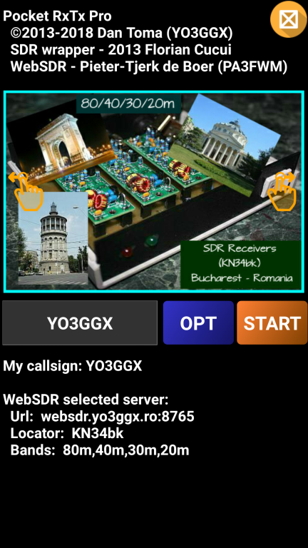
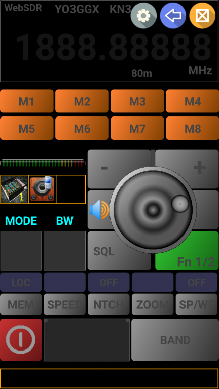
NOTE: The application screen is designed for both landscape and portrait operation. Landscape is usually used for tablets and portrait for smartphones. To reduce the size of the user guide, mostly landscape mode screenshots will be presented. The content of the screen is similar in portrait mode. The same controls and information are available whether in portrait or landscape screen mode.
On the WebSDR setup page, you can see a picture that is associated with the server picture. Clicking on it will give more information as provided by the server owner.

Click on the blue
BACK icon
![]() to return to the setup page.
to return to the setup page.
Clicking on the green text in the lower part of the screen, a FAQ page about WebSDR server will be opened.

Again, click on the
blue BACK icon
![]() to return to the setup page.
to return to the setup page.
In the lower left part of the screen you can see the available frequency bands/ranges on the selected server.
Clicking on the server QTH its and your and location will be displayed in a message box with the distance away from you that the WebSDR is located. For this function, Location Access Permission is required to be granted in Android (you will be prompted to allow access to location).
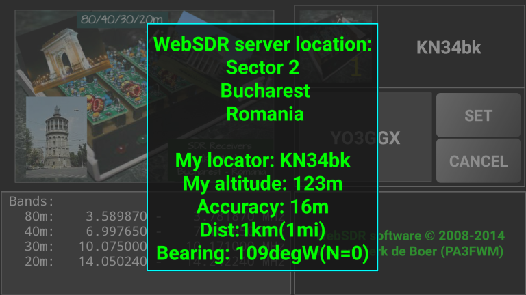
Click on the green text to return to the setup page.
NOTE: Anytime a message box is displayed on the screen, you can click on it to remove it.
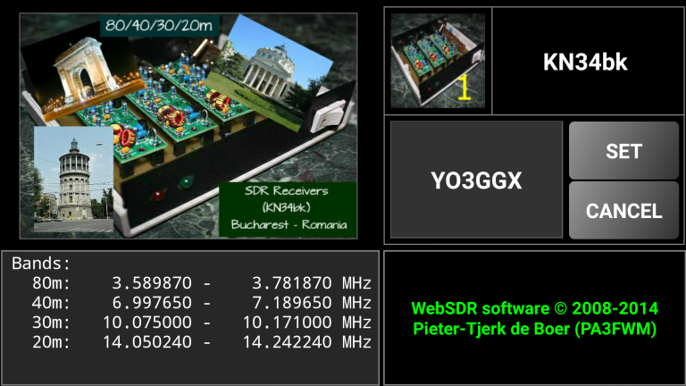
If you click on the server callsign or on the server logo (icon) from the setup page, a selection page will be displayed with all of the WebSDR servers that are currently registered with Pocket RxTx (in alphabetical order).
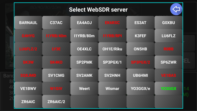
The color code for the text is as follows:
Red – server currently offline or unreachable (cannot be selected)
White – available online server
Green – currently selected server
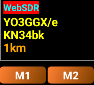
To select a different server to the current one, click on the button with the required server callsign on it (in white text).
Let’s click for example on YO3GGX/e. The newly selected server info is displayed.
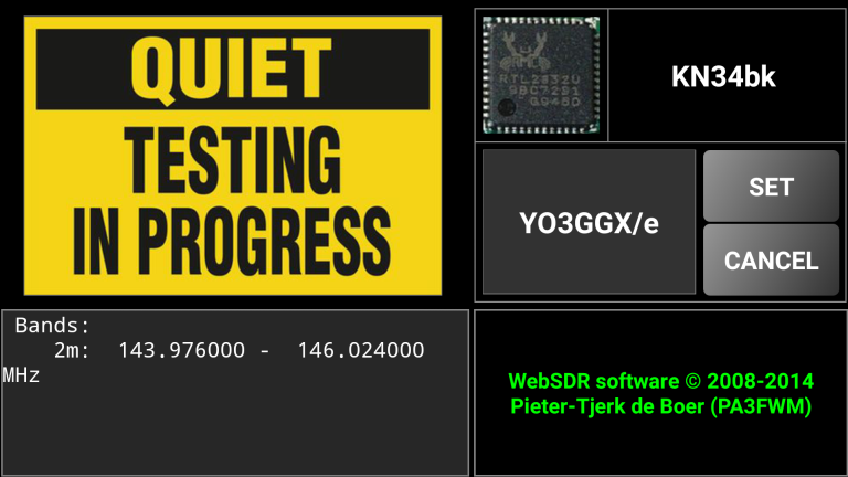
To use this server, click on SET button. To revert to the previous server, click on CANCEL.
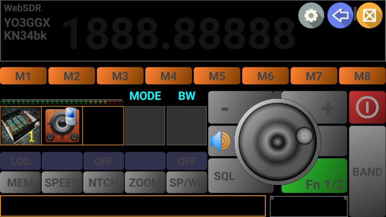
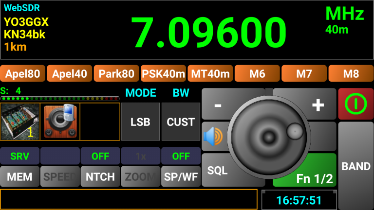
To start reception long press the red power button in the startup page. The screen will change as shown below:
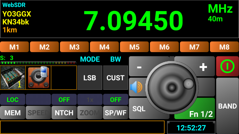
The screen contains the following controls/information:
“WebSDR” mode displayed in the top left corner in cyan;
WebSDR server callsign (YO3GGX);
WebSDR server location (KN34bk);
Approximative distance between your current location and server location
A big light green display for the receiver frequency;
Currently selected HAM band (if any);
S-meter level bar meter. The numerical value for S is displayed above it;
8 memory buttons used to store all the settings (Freq, mode, info, etc.) – these are extended to 16 memories if you press the green FN (function) button and select set 2;
A gray box displaying and allowing change to the current mode (LSB/USB/CW/AM/FM). Any change will be sent to the server in real-time.
A gray box displaying and allowing change to the current bandwidth (Normal/Narrow/Wide/Custom);
+ and – buttons to increase/decrease received frequency with a step depending on the current HAM band. By keeping one of these buttons pressed, you will enter a “Repeat” mode allowing the frequency to be changed faster;
A rotary knob which can be used for tuning, the same as on a real transceiver. When rotating slowly, the step is 10Hz, when rotating faster the step is higher;
An ON/OFF (power) red button used to turn ON or OFF the connection to the WebSDR server. When OFF, the display will be completely dimmed and buttons other than the power button locked;
The Function (FN) button is used to switch between the two groups of memories (M1-M8 or M8-M16);
A gray button named MEM, used to switch between local and server-based memories;
A gray button named SP/WF, used to select between large frequency digits, a Waterfall or Spectrum display;
A gray button named “NTCH”, used to activate the notch filter (server-dependent feature);
A gray button named “ZOOM”, used to zoom into the Waterfall or Spectrum display, available only when in Waterfall or Spectrum mode;
A gray button named “SPEED”, used to select Waterfall or Spectrum refresh speed, available only when in Waterfall or Spectrum mode;
An orange box in the bottom of the screen used to display custom or debug info (when available). This info is stored in memory;
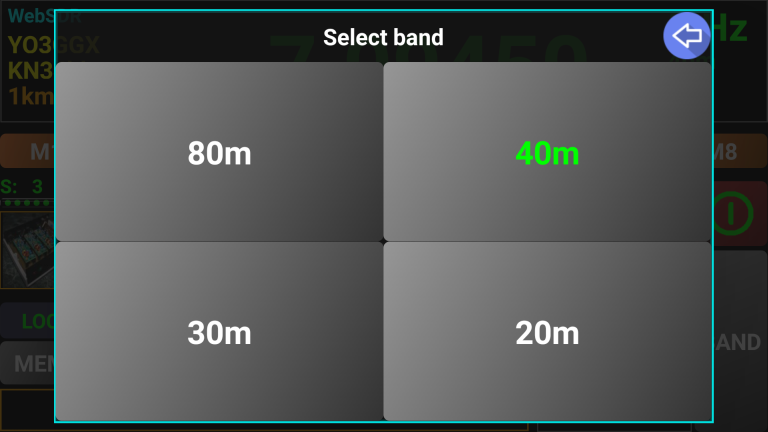
A BAND button which is used to change the band received. When you press on this button, only the available bands for the currently selected server are displayed. You can select any available band by clicking on the corresponding button. The currently selected band is displayed in green;
You can also directly enter the frequency you want (in MHz). Simply click on the frequency display to activate the numeric keypad.
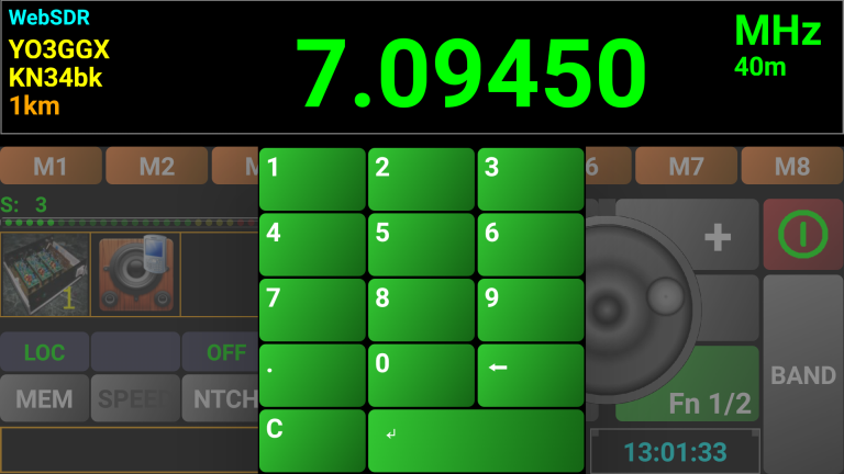
A numeric keypad is overlaid. Simply
enter the desired frequency and then click on the ENTER button
![]() .
.
To delete the last digit, click on the
BACKSPACE button
![]() .
.
To delete the whole entry, click on the
CLR button
![]() .
.
Once you have selected and connected to a WebSDR server, the distance from your location to that WebSDR server is displayed on the main page. This may be helpful when checking your Tx performance or propagation.
![]()
To access the waterfall or spectrum
display, click on the SP/WF button
![]() .
You will be prompted to select between two waterfall modes (black and
white or color) or spectrum.
.
You will be prompted to select between two waterfall modes (black and
white or color) or spectrum.
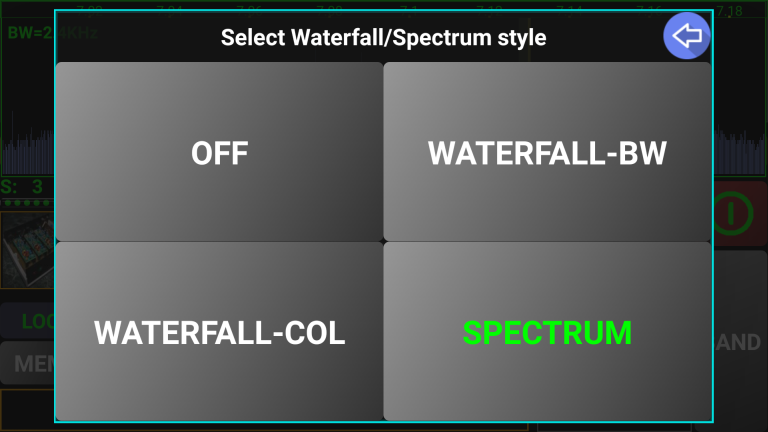
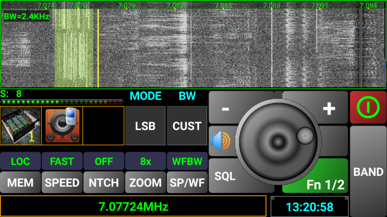
The top part of the screen will now be used for the waterfall or spectrum scope.
Color waterfall
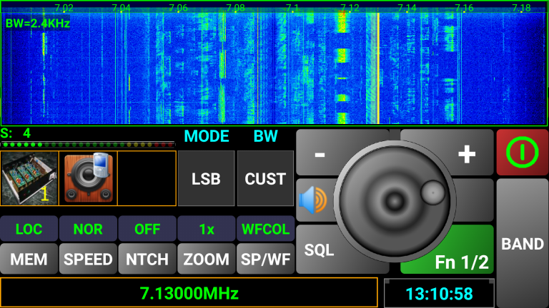
Black and white waterfall
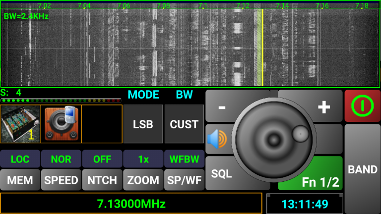
Spectrum scope
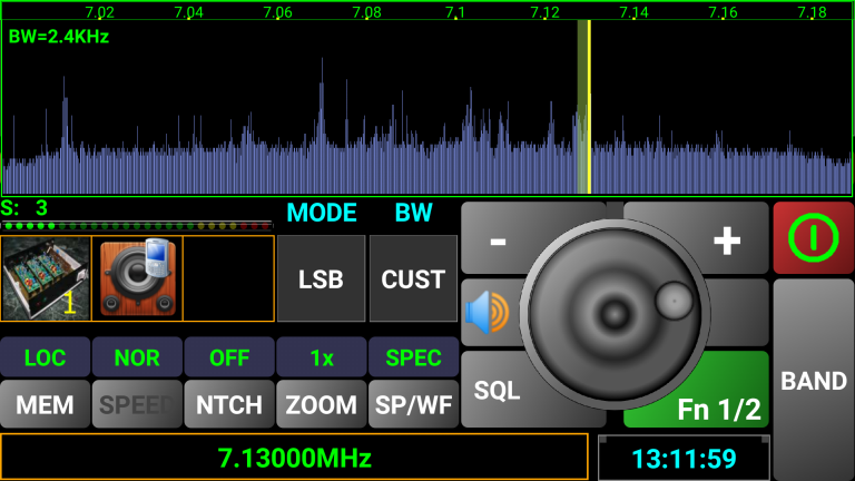
The currently received frequency will be displayed now in the info box at the bottom of the screen.
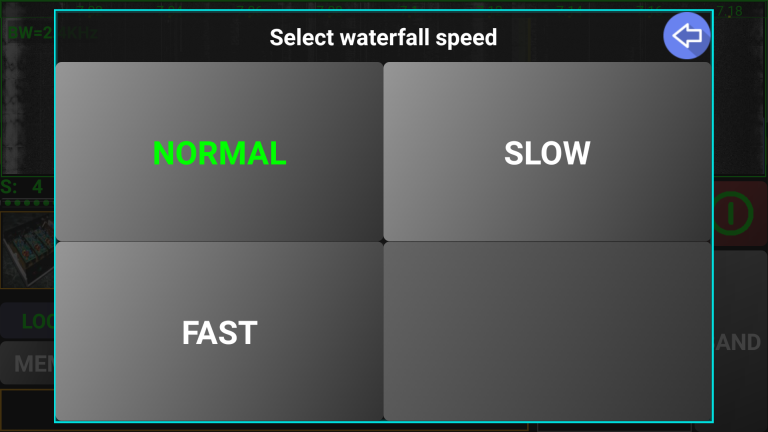
While in the waterfall mode, you can
click on the SPEED button
![]() to select between NORMAL, SLOW or FAST speeds.
to select between NORMAL, SLOW or FAST speeds.
The currently tuned frequency will be represented by a vertical yellow marker and the current bandwidth by a semitransparent green strip. A frequency scale is displayed at the top of the waterfall/spectrum display.
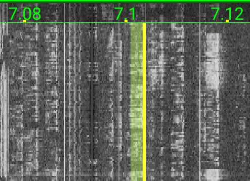
To select a frequency, you can directly touch the waterfall/spectrum scope or drag the yellow marker to tune to a specific frequency. Fine tuning can then be done using the tuning knob.
You can zoom into the display by clicking the ZOOM button on the lower part of the screen and you will be prompted to select the desired ZOOM level.
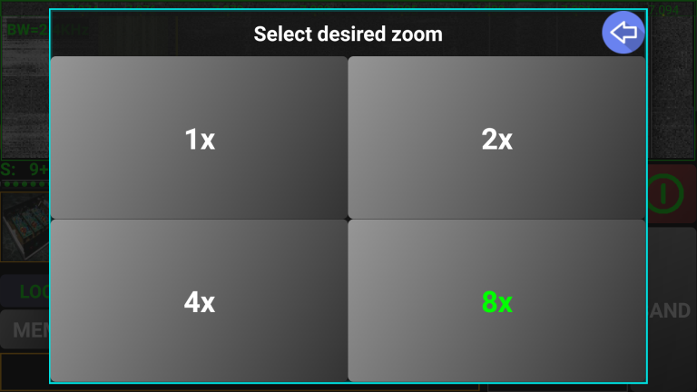
Depending on the available bandwidth for the selected HAM band, you can have a maximum zoom between 2x and 64x. As an example, for a 192 KHz bandwidth display you will have a maximum zoom of 8x, for 96 KHz a maximum of 4x and for a 2MHz bandwidth (usually on WebSDR servers using an RTL2832 module) a maximum zoom of 64x. The frequency scale will change in line with the zoom factor selected. The zoom feature can be very useful if you tune in the CW section of a band where the bandwidth is very small, as shown below. A long press of the ZOOM button will automatically reset the zoom factor to 1x.
You have 4 presets for the bandwidth in WebSDR client mode, depending on the chosen mode, as follows:
AM:
Narrow: +/- 2.5 KHz
Narrow2: +/- 2 KHz
Normal: +/- 3 KHz
Wide: +/- 3.5 KHz
SSB:
Narrow: 0.2 – 2 KHz
Narrow2: 0.2 – 1.5 KHz
Normal: 0.3 – 2.7 KHz
Wide: 0.2 – 3.5 KHz
CW:
Narrow: 0.72 – 0.78 KHz
Narrow2: 0.73 – 0.77 KHz
Normal: 0.6 – 0.9 KHz
Wide: 0.55 – 0.95 KHz
FM:
Narrow: +/- 5 KHz
Narrow2: +/- 3 KHz
Normal: +/- 8 KHz
Wide: +/- 25 KHz
CUST:
This setting indicates that the bandwidth is defined from a setting in memory (local or server based). In the current version of PocketRxTx you cannot edit the bandwidth from within the app.
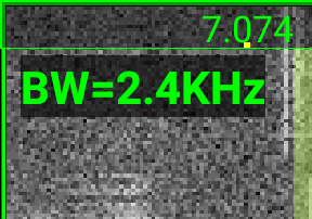
The current selected bandwidth is displayed in the top left corner of the waterfall, as shown here:
By default, the received sound is passed through the smartphone/tablet speaker. The currently used audio device is indicated by an icon:
![]() Phone
speaker
Phone
speaker
![]() Wired
headset
Wired
headset
![]() USB
headset/speaker
USB
headset/speaker
![]() Bluetooth
headset
Bluetooth
headset
Wired and Bluetooth headsets are automatically detected when connected/disconnected. In the current application version, a USB headset/speaker is detected only when connecting to/disconnecting from the WebSDR server.
Click on the MEM button to switch between local and server-based memories. Usage of local memories is presented in a separate chapter here, as this is common for both WebSDR and Direct CAT modes. If server-based memories are available on the selected server, then you will see the name of the memories on the memory buttons labels.
Click on any of the available memories to load the following stored parameters:
Frequency
Mode
Bandwidth limits. BW button will automatically change to CUST (Custom).
Information about that specific channel in the lower part of the screen
If the selected WebSDR server does not provide server-based memories, a message will be displayed if you try to access them.
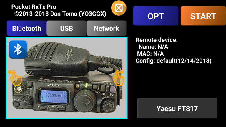
After loading a new radio configuration, you select in the startup page which connection mode (Bluetooth, USB/Serial or Network) is to be used for the new radio. Depending upon the selected mode, the display will look like one of the following images.
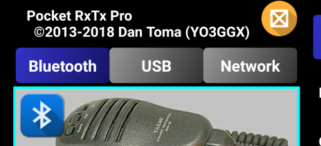
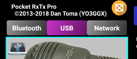
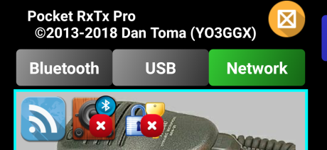
Please keep in mind the colors: blue for Bluetooth, magenta for USB/Serial and green for network. Certain icons will be displayed over the transceiver image. The first one represents the connection mode, second and third (only when using network mode) are audio and login authentication settings. Click the desired connection mode, then click the START button.
The main screen will appear as shown in the following picture (in network mode).
The possible icons are explained in the following table.
|
1st icon - Connection mode |
Network |
|
|
USB/Serial |
|
|
|
Bluetooth |
|
|
|
2nd icon - Audio Status |
Audio ON |
|
|
Audio Off |
|
|
|
3rd icon - Authentication |
Secure Authentication ON |
|
|
Secure Authentication OFF |
|
You can enable or disable audio and/or login authentication by clicking on the respective icons.
Over the audio icon, you can see a smaller icon representing currently used audio output device. For more details, see here.
CAT operation of the transceiver is identical for all 3 connection modes. The only major difference is the fact that audio is only supported when connected over a network.
To connect to the radio (over the selected interface), long press the red power button. If the connection is successful, the symbol from the power button will go blue (for Bluetooth connection), magenta (for USB connection) or green (for network connection.
![]()
![]()
![]()
You can control frequency, mode, output power, Band, VFO (A/B), Noise Blanker, PTT and any other parameter which is supported through CAT commands for your radio. If not already defined in an existing config file for you radio, you can define it yourself by editing the text file containing the radio configuration details. For more details click here.
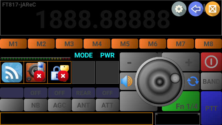
The option button has a status indicator field above it to indicate its state e.g. off/on.
You can have as many sets of five option buttons. The sets are selected through the green Fn (Function) button. This button will show you the available sets that are configured.
![]()
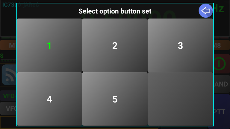
In the picture below, we have 5 sets, meaning 25 possible CAT commands through the 5 option buttons. The current set selected is indicated by the green text. You can switch between the sets with a press on the Fn button. The selection panel will allow you to choose the desired option set
There is another option button (per set) located at the lower left corner of the tuning knob. This is a special one, as there is no status indicator associated with it, you must take this into consideration when you assign a CAT command to this button.
The value of the number of sets (in the radio’s configuration text file) not only controls the number of option buttons, but also the number of banks of frequency memories. So, in this case, you have the ability to record 5x8=40 frequencies (with all the other associated parameters) to buttons.
NOTE: To keep compatibility with older configuration files, if the number of sets is not defined in the configuration file, you can only configure two sets (16 memories and 10 option buttons + 2 special buttons).
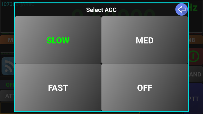
Any command available through CAT for your specific transceiver may be programmed on any option button. Depending on the number of possible states for each option button, a click action will behave differently. If you have just a single state for an option button (e.g. Tune), a message will be displayed to confirm the command was received. The option button label does not change. If you have a two-state option button (e.g. ON/OFF), then when you click the button, the option status indicator will be updated to confirm the command was received. For multi-state buttons, you are prompted with a selection panel. Let’s take for example AGC.
Another type of control are slider controls. With these controls you can set a value between defined min and max values. Let’s take for example RFGAIN.
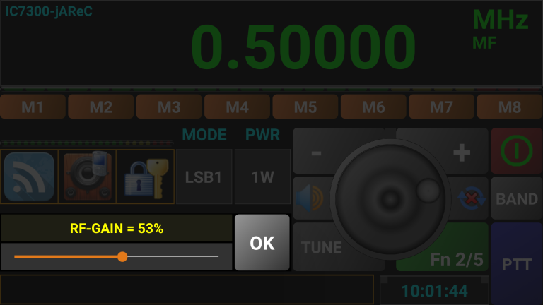
When you press a slider function button, a slider will be displayed. The values are always displayed in percentage (%), from 0 to 100. Use the slider to set the desired value for the parameter and then click OK to set that value through the CAT command to the transceiver.
If you want to read some parameters from the radio and set the Pocket RxTx GUI accordingly, you need to use feedback functionality. By default, at first start, radio feedback is deactivated. Status is then kept in the radio profile file. This functionality is controlled through the feedback button in the right part of the tuning knob.
Red ‘X’ means that the feedback is disabled. In order to be able to use radio feedback, read commands must be defined in the radio config file and POLLING line most be populated with all these read commands. Clicking on the button, you can toggle radio feedback on/ff. When you connect to the radio for the first time, when you click on radio feedback button, you are prompted to select the parameters you want to be read from the radio. Let’s take as example v3 of IC7300 config.
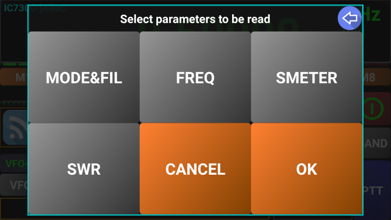
You can select any number of parameters to be read from the radio. Let’s consider that we want to read the status for frequency, mode and filter. Click on FREQ and MODE&FIL buttons, that will turn green.
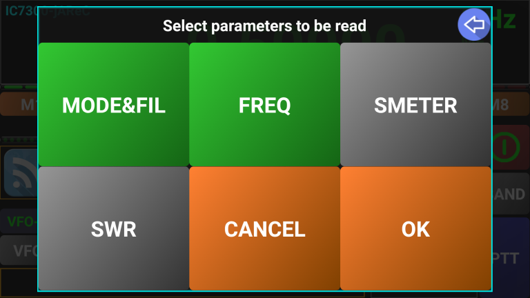
After you select all desired parameters, click on OK. If you want to return without selecting any parameter, click on CANCEL. Let’s click on OK. The radio feedback button shows that the polling is now working.
NOTE: Two virtual LEDs, in the upper left (Tx - yellow) and right (RX - white) of the UTC clock shows when data is transmitted to or received from jAReC.
Tx data Rx data


See the chapter dedicated to the radio configuration file here for more details about how to define or edit read commands and POLLING line.
There is a feature implemented for the PTT button. If you press on PTT button, the transceiver will go in Tx mode till you release it, like on a normal transceiver. If you press and slide your finger vertically over the PTT button (more than 1/3 of the button height), the PTT will enter sticky mode. The transceiver will remain in Tx till you press the button again or if a timeout defined in jAReC occurs. This sticky mode can be useful when you need to talk and to have the hands free.
You have two sets of memories (M1-M8 and M9-M16) for each available WebSDR server and a user configurable number of sets for direct CAT mode. The procedure to use memory buttons is the same for both WebSDR client and Direct CAT modes.
Each memory location saves the state of all defined option buttons (if more than one state), of the two main option buttons (usually mode and power, but can be redefined by the user) and the frequency. To save to a specific memory location, configure the transceiver for all the parameters and then long click on one of the memories buttons (ex. M1).
You will be prompted to enter the label for the selected memory button (memory name) and a description for that location, separated by a comma. Click OK after you check entered data. If you want to discard data, click on CANCEL. If the memory location was previously defined, you can clear that location by clicking on CLEAR.
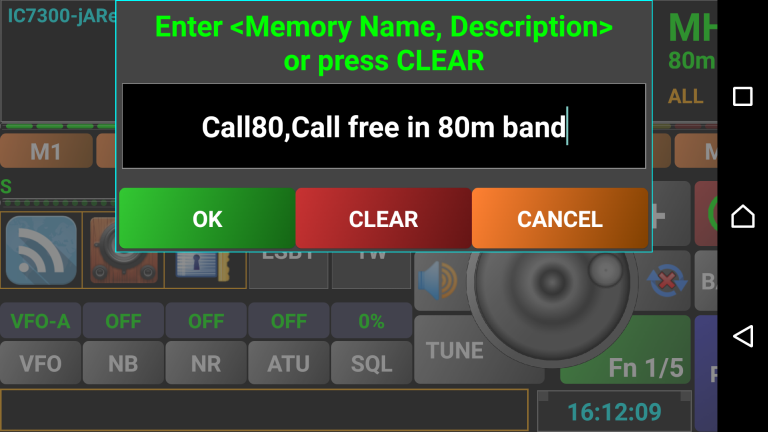
Data is saved to memory button 1. Description is not mandatory and can be omitted.
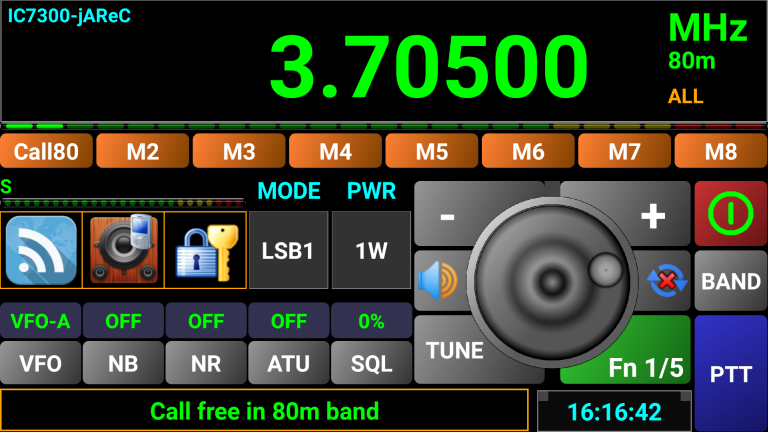
The button label will change and the description will be displayed in the info box (lower part of the screen).
To recall a memory location, you just have to click on the corresponding button. All the settings saved for that location will be restored and the option buttons status synchronized with the saved values. Several CAT commands will be automatically sent to the radio in order to set the status according with all the option buttons (from all sets).
To clear a memory location, you have to long click on the corresponding button and when asked to enter name and alias just click on CLEAR button, or delete everything and click OK. The memory button will be renamed to the original Mx.
You have the possibility to log calls directly on your device.
NOTE: This feature is available in the free version of the application only in the WebSDR client mode.
In order to use call logging, you must first configure this feature, through the OPT button in the startup screen. Check here to learn how to do it.
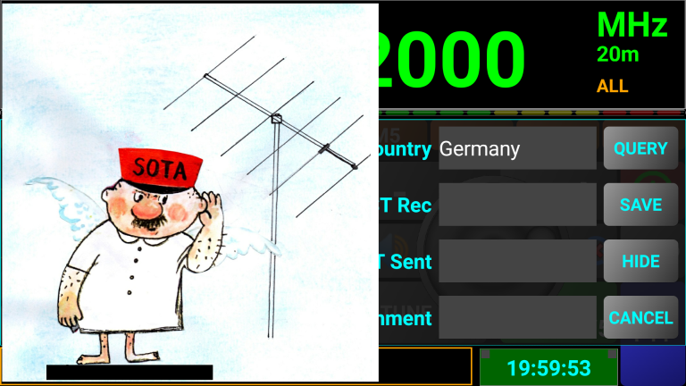
When radio is on, click on the UTC clock area to start logging for the current call. An overlay frame will be displayed allowing you to enter basic information for the call. The UTC clock background will go green, to show you that you are in call logging mode.
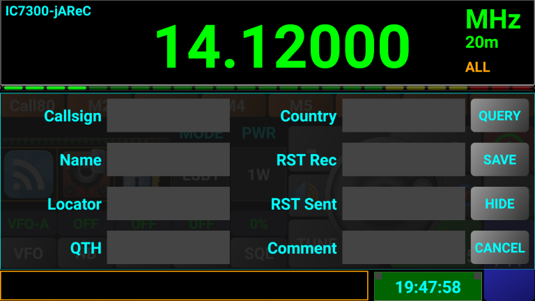
The call start time is set now. Enter the callsign of the corresponding party and press NEXT.
If you previously entered QRZ credentials, all available data for that callsign (Name, Locator, QTH and Country) is filled-in automatically.
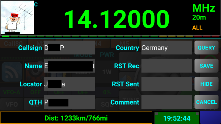
If a picture of your correspondent is available in QRZ, this will be displayed in the upper left corner of the screen.
You can toggle between small and large picture by just clicking on it.
If the picture for that person is not available in his QRZ entry, a generic picture will be displayed.

You need to manually fill some fields: RST Rec (communicated by the correspondent), RST Sent (the one you sent to the correspondent) and a comment (optional). If you want to operate the radio during the call, click on HIDE button to toggle the call log entry form on/off. The UTC time background color will remain green during this time, to show you that you are in call logging mode.
![]()
If you encountered a network error when the automatic query was started, you can manually force a new query by clicking on QUERY button. The only required field for this is the callsign.
If you entered QRZ logins and enough location information is available for both you and your correspondent (coordinates or locators), then the distance to the corresponding station is displayed in the info bar (in both km and miles.
![]()
Now you have some other options. You can save the call information in the local call log by clicking on SAVE button. The information for the current call will be appended to the existing log file. If no local call log file available, a new one will be automatically created, in ADIF format, with standard header information. A short message will be displayed showing that the info was saved. The end call time is set now. Time used is UTC time. You can have maximum one local log file at any moment. Multiple files are not supported. The standard format for the call log file name is the following:
logbookyyyyMMddhhmmss.adi where:
yyyy – year
MM – month (01-12)
dd – day (01-31)
hh – hour (in 24h format)
mm – minute (0-60)
ss – second (0-60)
when the call log file was created (UTC time).
After you transfer the log file by e-mail or by using CFG EXP function, you have the possibility to remove locally stored log file using DELETE function from CALLLOG menu.
If you want to cancel call logging for the current call, you can long press on the UTC clock to cancel it. A short message will be displayed showing that call logging mode was canceled.
The call log file is stored internally in the application folder, but can be exported (see CFG EXP) or sent by e-mail (see E_MAIL)
The created ADIF file is based on the specifications for the version 3.0.8 from here:
http://www.adif.org/308/ADIF_308.htm
Only the following fields are added to the log if available (from QRZ database or from a local entry in the call log form):
ADDRESS - contacted station's complete mailing address
AGE - contacted station's operator's age in years in the range 0 to 120 (inclusive)
BAND - QSO Band
CALL - contacted station's Callsign
COMMENT - comment field for QSO
COUNTRY - contacted station's DXCC entity name
CQZ - contacted station's CQ Zone in the range 1 to 40 (inclusive)
DISTANCE - the distance between the logging station and the contacted station in kilometers. This is calculated in the application based on latitude and longitude (if available) or on maidenhead grid squares.
DXCC - contacted station's DXCC Entity Code
EMAIL - contacted station's email address
FREQ - QSO frequency in Megahertz
GRIDSQUARE - contacted station's 2-character, 4-character, 6-character, or 8-character Maidenhead Grid Square
IOTA - contacted station's IOTA designator
ITUZ - contacted station's ITU zone in the range 1 to 90 (inclusive)
LAT - contacted station's latitude
LON - contacted station's longitude
MODE – QSO Mode
MY_CITY – my station’s city
MY_COUNTRY – my station's DXCC entity name
MY_CQ_ZONE – my station's CQ Zone in the range 1 to 40 (inclusive)
MY_DXCC – my station's DXCC Entity Code
MY_GRIDSQUARE – my station's 2-character, 4-character, 6-character, or 8-character Maidenhead Grid Square
MY_IOTA – my station's IOTA designator
MY_ITU_ZONE - my station's ITU zone in the range 1 to 90 (inclusive)
MY_LAT – my station's latitude
MY_LON – my station's longitude
MY_NAME – my name
MY_POSTAL_CODE – my station's postal code
NAME - contacted station's operator's name
QTH - contacted station's city
TIME_OFF - HHMM or HHMMSS in UTC
TIME_ON - HHMM or HHMMSS in UTC
TX_PWR – my station's power in Watts
WEB - contacted station's URL
To build all ADIF record fields, the following data is extracted from the QRZ database, for both my station and for the contacted station (as described in https://www.qrz.com/XML/current_spec.html):
call - callsign
dxcc - DXCC entity ID (country code) for the callsign
fname - first name
name - last name
addr1 - address line 1 (i.e. house # and street)
addr2 - address line 2 (i.e, city name)
zip - Zip/postal code
country - country name for the QSL mailing address
lat - lattitude of address (signed decimal) S < 0 > N
lon - longitude of address (signed decimal) W < 0 > E
grid - grid locator
email - email address
url - web page address
image - full URL of the callsign's primary image, used just to display the picture in the Pocket RxTx GUI, not stored
cqzone - CQ Zone identifier
ituzone - ITU Zone identifier
born - operator's year of birth
iota - IOTA Designator (blank if unknown)
For each transceiver available in direct CAT mode two files are required:
A configuration file with the filename < brand>_<model>.radio (ex. yaesu_ft450.radio)
A 480x320 JPG image representing the radio, with the filename <model>.jpg (ex. ft450.jpg)
All filenames are lowercase.
NOTE: You can edit the transceiver configuration files only after exporting them using CFG EXP button to a PC, Mac or Linux computer through jAReC, over the network.
The file is based on the following general structure for each line: <parameter>=<values>.
NOTE: Anywhere in the file you can enter comments by starting the line with the “;” char.
The radio configuration file has the following structure (explanation with the example of the Icom IC7300 configuration file)
Brand=Icom
Model=IC7300
Pic=ic7300.jpg
sigRadios=$1gR@d10s
CATPROTOCOL=http://www.plicht.de/ekki/civ/index.html
; Number of sets for the option button and memories
SETS=5
Brand – the brand of the transceiver;
Model – the model of the transceiver;
Pic – the filename of the radio image file (480x320 jpeg);
sigRadios – a special signature used to recognize this as a radio configuration file. This must be the same for all radios;
CATPROTOCOL – a link to a web page where the CAT protocol for the radio can be found;
SETS – the number of option buttons/memories sets. Ex: if this value is 5, you have 5x5=25 options buttons, 5 special buttons (SQL) and 5x8=40 memories.
; Frequency coverage (sections separated by ',')
; format: FRANGE=f1-f2,f3-f4,f5-f6,...
FRANGE= 30000-74800000
; Frequency step per frequency range, in KHz, freq range in Hz
; format: FSTEP=<brute_step1>/<fine_step1>=<freq_interval1_min>-<freq_interval1_max>,<brute_step2>/<fine_step2>=<freq_interval2_min>-<freq_interval2_max>, ...; brute - for +/-, fine for knob tunning
FSTEP=1/0.1=100000-87499999
; List of available Bands
BANDS=160m,80m,60m,40m,30m,20m,17m,15m,12m,11m,10m,6m
BANDSA=
BANDSB=
FRANGE – some radios do not have a continuous frequency coverage. You can add here all frequency segments (defined by <start_freq_Hz>-<end_freq_Hz). Segments are separated by “,” char. You can add as many segments you want. Do not use <CR> or <LF> control chars inside the line, even if the line is very long.
FSTEP – here you can define the frequency steps (fine – when tuning by the knob, or brute – when tuning by Up/Down buttons). The steps can be defined separately for as many frequency segments you want, but you must take care that the full radio frequency range is covered, otherwise internal default values are used for the undefined segments
BANDS – list of transceiver available HAM bands, when is the same for both VFOs. This will determine which bands you can select when you press BAND button in the main app interface.
BANDSA, BANDSB – For some transceivers (like Kenwood TH-F6/7) available bands are different for each VFO. In this situation you need to use separate values for each VFO, using the following parameters:
BANDSA=
BANDSB=
NOTE: Only BANDS or (BANDA and BAND) must be filled in.
; first selection button - usually the list of available modes in the MODE wheel (starts with wheel name)
LST1NAME=MODE
LST1ITEMS=LSB1,LSB2,LSB3,LSB-D,USB1,USB2,USB3,USB-D,AM1,AM2,AM3,CW1,CW2,CW3,RTY1,RTY2,RTY3,FM1,FM2,FM3,CWR1,CWR2,CWR3,RTR1,RTR2,RTR3
LST1CMDS=CMD_SET_MODE_LSB_FIL1,CMD_SET_MODE_LSB_FIL2,CMD_SET_MODE_LSB_FIL3,CMD_SET_MODE_LSB_FIL2_DATA,CMD_SET_MODE_USB_FIL1,CMD_SET_MODE_USB_FIL2,CMD_SET_MODE_USB_FIL3,CMD_SET_MODE_USB_FIL2_DATA,CMD_SET_MODE_AM_FIL1,CMD_SET_MODE_AM_FIL2,CMD_SET_MODE_AM_FIL3,CMD_SET_MODE_CW_FIL1,CMD_SET_MODE_CW_FIL2,CMD_SET_MODE_CW_FIL3,CMD_SET_MODE_RTTY_FIL1,CMD_SET_MODE_RTTY_FIL2,CMD_SET_MODE_RTTY_FIL3,CMD_SET_MODE_FM_FIL1,CMD_SET_MODE_FM_FIL2,CMD_SET_MODE_FM_FIL3,CMD_SET_MODE_CWR_FIL1,CMD_SET_MODE_CWR_FIL2,CMD_SET_MODE_CWR_FIL3,CMD_SET_MODE_RTTYR_FIL1,CMD_SET_MODE_RTTYR_FIL2,CMD_SET_MODE_RTTYR_FIL3
LST1NAME – the name which will appear on top of the first selection button (usually MODE);
LST1ITEMS – the list of the available operation modes, separated by the “,” char;
LST1CMDS – list of the commands, separated by the “,” char, to set the modes from the previous list. You must take care to respect the same position in the enumeration;
; second selection button - usually the list of available powers in the PWR selection button
LST2NAME=PWR
LST2ITEMS=1W,5W,10W,25W,50W,100W
LST2CMDS=CCMD_SET_PWR_1W,CMD_SET_PWR_5W,CMD_SET_PWR_10W,CMD_SET_PWR_25W,CMD_SET_PWR_50W,CMD_SET_PWR_100W
LST2NAME – the name which will appear on top of the second selection button;
LST2ITEMS – the list of the output power values to appear in the list;
LST2CMDS – the list of the commands, separated by the “,” char, to set the corresponding power levels from the previous list. You must take care to respect the same position in the enumeration;
BTN_OPT1_NOFN=VFO,CMD_SET_VFO-A=VFO-A,CMD_SET_VFO-B=VFO-B
BTN_OPT2_NOFN=NB,CMD_SET_NB_OFF=OFF,CMD_SET_NB_ON=ON
BTN_OPT3_NOFN=NR,CMD_SET_NR_OFF=OFF,CMD_SET_NR_ON=ON
BTN_OPT4_NOFN=ATU,CMD_SET_ATU_OFF=OFF,CMD_SET_ATU_ON=ON
BTN_OPT5_NOFN=SQL,CMD_SET_SQUELCH=FOO
BTN_SQL_NOFN=TUNE,CMD_SET_ATU_TUNE=[Tuning...]
…
BTN_OPT4_FN=AGC,CMD_SET_AGC_SLOW=SLOW,CMD_SET_AGC_MEDIUM=MED,CMD_SET_AGC_FAST=FAST,CMD_SET_AGC_OFF=OFF
For each button (OPT1 to OPT5, based on the option set selected through the Fn button) the structure of the line is the following:
<btn_name>_<Fn_status>=<btn_caption>,<cmd1>=<option_display_for_cmd1>,<cmd2>=<option_display_for_cmd2>,<cmd3>=<option_display_for_cmd3>,<cmd4>=<option_display_for_cmd4>…
BTN_SQL - the one in the lower left part of the tuning knob, can be used as a standard option button (one for each set), but without a label associated with it. Because of this, you must take care to allocate only single state commands to this button (for example TUNE). This is not mandatory, but you will not see the current status for this button.
For backward compatibility with older versions of the application (supporting only two option sets), <Fn_status> parameter is represented as follows:
NOFN - option set 1
FN – option set 2
FN2 – option set 3
FN2 – option set 4
….
Each button from each set can have 1, 2 or multiple states. In the example above, NB (noise blanker) button has two states: ON/OFF. The AGC (auto gain control) has 4 states OFF/SLOW/MED/FAST. The status following each command execution is displayed on top of the corresponding option button.
A definition example for a single state button is TUNE. The format is:
<btn_name>_<Fn_status>=<btn_caption>,<cmd>=[<message>]
If such a button is pressed, the associated command is sent and the message is displayed for a few seconds.
Another special definition is for the buttons associated with parameters that can have any integer value between min and max. For these buttons, sliders are used to set the desired value for the parameter. See slider commands later in the document. The format is:
<btn_name>_<Fn_status>=<btn_caption>,<cmd>=FOO
When such a button is clicked, a slider window is open.
; Hardware keys definition
; you can assign device hardware keys to send specific CAT commands
KEY1CODE=25
KEY1_DOWN=CMD_SET_PTT_ON
KEY1_UP=CMD_SET_PTT_OFF
KEY2CODE=
KEY2_DOWN=
KEY2_UP=
KEY3CODE=
KEY3_DOWN=
KEY3_UP=
You can define up to 3 hardware buttons to execute specific CAT commands for the two possible events. By default the first key definition is used for PTT and can be configured from the application interface. See here for more details.
To find the Keycode you can use the GUI to define the PTT key. For each event you can define a CAT command using standard format.
These commands are used to set different parameters in the radio and the name always must start with “CMD_SET_...”.
As new features will be added to the application, this section will be extended. The general format of each line from this section is the following:
<cmd >=<byte1>,<byte2>,<byte3>…..
The bytes are effectively transmitted over CAT only after the full command is rebuilt inside the application. Exception is when one of the bytes represent the special ‘pause’ byte (see below).
Now, the byte can be represented in several ways.
by his hexadecimal representation (2 hex chars): ex. : 13,A2,FF,9D
by a non hexa (direct) representation. In this case the full byte is included between ‘<…>’. First character after ‘<’ reprezents the type of data which follows, and can be:
<S…> – String – followed by one to an unlimited number of chars. Each character represent the byte to be transmitted;
Example (Elecraft K3):
CMD_SET_MODE_LSB=<SMD1;>
This command will send the following string: ‘MD1;’
<Cx> – Char digit. This is used to transmit frequency values and is followed by a number (x) which can be 0 – Hz, 1 – tens of Hz, 2 – hundred of Hz, …., 8 – hundred of MHz, 9 – GHz;
Example (Elecraft K3):
CMD_SET_FREQ_VFO-A=<SFA>,<C7>,<C6>,<C5>,<C4>,<C3>,<C2>,<C1>,<C0>,<S;>
If the frequency is 14.120MHz this command will send the following string: ‘FA14120000S;’
<Dxy> – BCD digit. This is used to transmit frequency values and is followed by 2 numbers (x and y from 0 to 9), same as above, as two digits are packed for each byte;
Example (Yaesu FT817):
CMD_SET_FREQ=<D87>,<D65>,<D43>,<D21>,01
If the frequency is 145.225MHz this command will send the following bytes sequence (represented as hex values): 14,52,25,00,01
<P> – Pause. This is a special identifier and is followed by 4 digits representing the pause time in milliseconds. If this special ‘byte’ is encountered, all the previous bytes are sent and then wait for the defined number of milliseconds and then build the next part of the command.
Example:
<P1000>
This will send previous bytes sequence from the command, insert a 1s pause and then go further for the next sequence(s) of bytes (which follows in the same line).
<WEaaaa;bbbbbbbb;cccccccc> – This command is used only for FT8x7 transceivers to write specific EEPROM memory location (some basic commands are undocumented and available only through direct EEPROM writing ).
Enter EEPROM location aaaa (as a 4 digits hex value), first byte (bbbbbbbb) and second byte (cccccccc) as binary values. Use only ‘0’, ‘1’ or ‘x’ for each individual bit value, (x) meaning to keep the old value unchanged.
Example:
CMD_SET_PWR_1.0W=<WE0079;xxxxxx10;xxxxxxxx>
This command will set bit 0 of memory location 0079 to 0 bit 1 to 1 and will keep unchanged the rest of the bits for the same memory location and for the next one (007A). The Write EEPROM command has two steps. In the first one previous values for the two successive EEPROM addresses are read and then only desired bits are changed and the updated values goes back to the EEPROM.
WARNING: It can be very dangerous to modify EEPROM locations. If you have not saved all the transceiver configuration before using this application is better not to use it with an FT8x7 transceiver. Although I took a reasonable number of precautions in the code, use this feature at your own risk!
A slider command has a specific format. Let’s take as example the RFGAIN command for iCOM IC7300:
CMD_SET_RFGAIN=@RF-GAIN,<MAX=255>,FE,FE,<A>,E0,14,02,<D32>,<D10>,FD
@RF-GAIN – RF-GAIN is the text to be displayed in the title of the slider window
<MAX=255> - 255 is the maximum value for the parameter. For the slider commands, minimum value is always 0.
FE,FE,<A>,E0,14,02,<D32>,<D10>,FD – is the command to be sent in order to set that parameter, where:
<D32>,<D10> is the parameter represented in a BCD packed format.
You can use as parameter <T2>,<T1>,<T0> if the value is represented as 3 chars (ex. For Yaesu FT450).
In the Pro version you can associate any option button with a remote script to be executed on the system where jAReC
In the Pro version you can associate any option button with a remote script to be executed on the system where jAReC runs. You can define up to 98 scripts (from ‘02’ to ’99). The format of the command is as in the following example:
BTN_OPT3_FN3=CMD,Command15=RUN
BTN_OPT4_FN3=NOTPD,Command02=RUN
Where “CMD” or “NOTPD” is the text to appear on the corresponding button, “RUN” is the text to appear on the label above the option button. When that button is pressed, the associated command is executed remotely. Check jAReC user guide to learn how to set the other end.
To get radio feedback, several read commands must be defined. The command name must always start with “CMD_READ_...”. A timer is used to execute read commands at a specific interval, which is dependent on the available CAT Baudrate.
The syntax is different than the one used for SET commands and is much more complex:
CMD_READ_...=<priority>,<when to read>,<command - variable length>,<separator>,<nr_of_expected_bytes>,<rec_byte_1>,...,<rec byte_n>
Like for the SET commands, there are several bytes separated by “,”
<priority> - byte to define when the command is executed. Currently possible values are: 01 – at each read timer tick, 02 – at each 4th read timer click. Use 02 for parameters which are not faster updated, like MODE.
<when to read> - byte defining if the parameter must be read during RX only (01), during TX only (02) or during both RX and TX (00)
<command - variable length> - this is the command to be send to read that specific parameter and can have a variable bytes length. The same syntax as for the SET commands is used. There is one more specific command available for this, which applies to Yaesu FT8x7 transceivers only: Read EEPROM value. The syntax of this command is the following:
<REaaaa> - Read EEPROM value from the address aaaa (as a 4 digit hex value).
This command returns 2 bytes, the value at address aaaa and at the next address (aaaa+1)
<separator> - as the command length is variable, wee need to know when the command definition is ended. We use ‘<R>’ char sequence as separator.
<nr_of_expected_bytes> - number of data bytes expected to be received for the read command. This a 2 digit hex number.
<rec_byte_x> - the way received byte number x is to be interpreted. The rule used here includes the definition for the SEND commands bytes, plus:
<00> - byte not containing useful data – to be discarded
<value_received=how_to_set_the_parameter> -
value_received can be represented as a 2 digits hex or a 8 digit binary value. When a binary value is used, possible values for each bit are ‘0’, ‘1’, ’v’ or ’x’. ‘v’ is used when a value span over multiple bits. You can have between 0 and 8 v’s in each binary represented bytes, but they must be contiguous. For example a succession of 4 v’s means that the value to be read is between 0000 and 1111 (from 0 to 15 decimal). ‘x’ means bit to be discarded. If several possible values are to be interpreted, separate them with ‘;’
To better understand how to use this, here are some examples from the Yaesu FT817 configuration file:
CMD_READ_SMETER=01,01,00,00,00,00,E7,<R>,01,<xxxx0000=S0;xxxx0001=S1;xxxx0010=S2;xxxx0011=S3;xxxx0100=S4;xxxx0101=S5;xxxx0110=S6;xxxx0111=S7;xxxx1000=S8;xxxx1001=S9;xxxx1010=S9+10dB;xxxx1011=S9+20dB;xxxx1100=S9+30dB;xxxx1101=S9+40dB;xxxx1110=S9+50dB;xxxx1111=S9+60dB>
This command will send at each read timer click (priority = 01), during RX only (when_to_read = 01) the following byte sequence: ‘00,00,00,00,E7’ and wait to receive one byte (nr_of_expected_bytes=01). The received byte is then interpreted as follow. Bit 7 to bit 4 are discarded (x) and for the rest (bit 3 to 0), depending on the specific values, set the S-meter accordingly: for 0000 set it to S0, for 0001 set it to S1, …. , for 1111 set it to S9+60dB.
CMD_READ_PTT=04,00,00,00,00,00,F7,<R>,01,<0xxxxxxx=ON;1xxxxxxx=OFF>
This command will send at each 4th read timer tick (priority = 04), during both RX and TX (when_to_read = 01), the following byte sequence: ‘00,00,00,00,F7’ and wait to receive 1 byte (nr_of_expected_bytes=01).
If bit 7 of the received byte is 0 then interpret this as PTT is active (ON). If is 1, interpret this as PTT is not active (OFF).
CMD_READ_PWR=01,02,00,00,00,00,BD,<R>,02,<vvvvxxxx>,<xxxxxxxx>
This command will send at each read timer tick (priority = 01), during TX only (when_to_read = 02), the following byte sequence: ‘00,00,00,00,BD’ and wait to receive 2 bytes (nr_of_expected_bytes=02). Keep only bits 7 to 4 from the first byte and compose a 4 bit numeric value (0 to 15 decimal). A numeric value is used normally to read one of the following parameters: S-meter, output power, SWR, ALC or MOD. In order to display useful values (standard S-level, power in W, standard SWR or percentage for ALC and MOD), some calibration parameters must be used. In some situations (ex S-meter for FT817) each S value correspond with a fixed received numeric value. Then the calibration data must be omitted (empty parameter)
Available calibration settings are: CALIB_SMETER, CALIB_PWR, CALIB_SWR, CALIB_ALC and CALIB_MOD.
The syntax for each calibration setting is the following:
‘xx=valxx’ – xx – received 2 digit hex value, valxx - parameter value corresponding to that received value. You can specify multiple points, useful when the value variation is not linear. For the intermediary values, linear interpolation is used to calculate that parameter real value. If latest value is not the highest possible value, any values greater than that one will be represented with “>”. This usually happen only for SWR parameter (ex. SWR > 10).
NOTE: If a parameter read definition contains ‘v’, then a calibration setting is mandatory). You can use Debug/Logging mode (see here) to read radio response to read meters commands in order to help you define calibration parameters for your specific radio.
You can define the list of commands you want to use in order to get feedback from the radio, using POLLING parameter, ex:
POLLING=CMD_READ_FREQ&MODE,CMD_READ_PTT,CMD_READ_VFO,CMD_READ_SMETER,CMD_READ_SWR,CMD_READ_PWR,CMD_READ_ALC,CMD_READ_MOD
You can read parameters that are represented by a numeric value in the radio answer. Let’s take as example the command to read S-METER for an iCOM IC7300 transceiver:
CMD_READ_SMETER=01,01,FE,FE,<A>,E0,15,02,FD,<R>,09,<00>,<00>,<00>,<00>,<00>,<00>,<D32>,<D10>,<00>
<D32>,<D10> is the BCD packed value for the parameter returned by the radio. You need then to define a calibration line:
CALIB_SMETER=<MAX=255>,<0=0;10=1;21=2;34=3;47=4;57=5;75=6;91=7;104=8;120=9;142=910;163=920;179=930;201=940;217=950;241=960>
Some radios use the numeric values represented by chars. Let’s take as example Yaesu FT450:
CMD_READ_SMETER=01,01,<SRM1;>,<R>,07,<00>,<00>,<00>,<T2>,<T1>,<T0>,<00>
and then the calibration line:
CALIB_SMETER=<MAX=255>,<0=0;25=1;38=2;52=3;70=4;90=5;102=6;120=7;135=8;150=9;170=910;189=920;197=930;214=940;225=950;235=960>
<Tx> - a number digit with position x (x = 2 –> hundreds, x = 1 -> tens, x = 0 -> units)
It is recommended not to use too many parameters as this will slow down the feedback.
Currently only the following feedback commands are implemented:
CMD_READ_FREQ&MODE (FT8x7 only)
CMD_READ_FREQ (not applicable to FT8x7)
CMD_READ_MODE (not applicable to FT8x7)
CMD_READ_PTT
CMD_READ_VFO
CMD_READ_SMETER
CMD_READ_PWR
CMD_READ_ALC
CMD_READ_SWR
CMD_READ_MOD
This is a list of commands to be sent after transceiver power up.
This is a list of commands, separated by ‘,’ using ‘STARTUP’ as name
Example:
STARTUP=CMD_SET_LOCK_OFF
Some commands are sent automatically when long pressing round blue power button inside the application: CMD_SET_POWER_ON and CMD_SET_POWER_OFF, if available.
NOTE: Not using feedback does not seems to generate lost sync, even at higher speeds, but make all the controls very responsive (ex. the tuning wheel).
You can define up to 3 hardware keys on your device with commands for the KEY_DOWN and KEY_UP commands.
For the PTT command, you can do this from the GUI. Click here for the procedure.
On standard Android devices, you can use any key except the STANDBY/ON one. Usually you can have VOL UP, VOL DOWN and (sometimes) CAMERA SHUTTER. Use hardware PTT procedure to find the keycode for a specific hardware button you want to assign. To define the other two optional hardware buttons, you need to edit the radio configuration file (see here for details).
If you want to change the radio address for an iCOM radio (the default one for your radio is automatically set by the application), in the startup page, short press on the info box in the right part of the screen. You will be prompted to enter/modify the address.
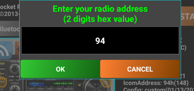
You can lock the interface of the application and the one of the transceiver (if CMD_SET_LOCK_ON and CMD_SET_LOCK_OFF CAT commands are defined). For this you need to long press on the green Fn button when radio is on.
The button caption will change to “LOCKED”.
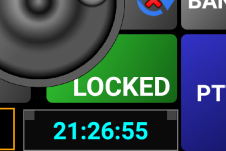
Long press the button again to unlock it.
There is a dedicated forum for this application on my web site here:
https://www.yo3ggx.ro/forum/viewforum.php?f=15
Please join it to discuss any details about Pocket RxTx. This will further help other interested users.
A video presenting all application features is available on YouTube. Please check my web page for the link.
Please subscribe to my channel (Dan Toma) to be automatically informed when a new video will be available.
The KA7OEI FT-817 pages - http://www.ka7oei.com/ft817_meow.html
Icom CI-V protocol - http://www.plicht.de/ekki/civ/civ-p0a.html
Kenwood PC control protocol - http://www.kenwood.com/i/products/info/amateur/ts_480/pdf/ts_480_pc.pdf
FT-450 CAT operation reference book - http://yaesu.com/downloadFile.cfm?FileID=2600&FileCatID=158&FileName=FT-450_CAT_Operation_Reference_Book.pdf&FileContentType=application%2Fpdf
Elecraft K3 and KX3 Programmer’s reference - http://www.elecraft.com/manual/K3&KX3%20Pgmrs%20Ref,%20E11.pdf
The following features are available only in the Pro (paid) version:
Does not contain ads
Support for scripts associated with buttons in Pocket RxTx (like CAT commands)
You can enable/disable interface animations, activated by default in the free version
Use full screen /immersive mode (hide navigation buttons) if Android >= 4.4 (KitKat)
Call logging in Direct CAT mode, not only in WebSDR client mode
If you set PTT timeout in jAReC, you are notified with a beep vibration (even if not activated from the SYSTEM option) when the transceiver was automatically switched to Rx when PTT timeout reached.
The free version is ad based, with the following specifics:
Ads banners are displayed in the startup page and in the main page when not connected to a radio, or to a WebSDR server.
A watermark in the startup page allows you to directly access the Pro version in Google Play Store
First release of the application in the current form.
What’s new/changed:
waterfall and spectrum added in SDR mode;
connection/power status LED replaced with a circular light around power button;
to toggle ON/OFF you have now to long press on Power button ;
mute button added;
waterfall/spectrum zoom (x1, x2, x4, x8);
you can now select the language for the online user manual or HELP menu;
exit menu added;
default font size is auto scaled based on device type/config;
other small cosmetic changes (ex. info frame background changed to Black, rounded buttons, gray background for help, etc.).
What’s new/changed:
feedback for PTT and S-Meter added in HRD mode
support extended to more functions/transceivers (see the table)
Bugs solved:
cannot change mode because of feedback from transceiver
in HRD mode the power is not read correctly at startup
if Off and then On does not connect anymore to HRD (need to restart app)
do not keep mode and bandwidth settings when rotating in SDR mode
sound dropouts in SDR mode
What’s new/changed:
USB CAT support in FT8x7 mode (Only FTDI and CP2102 based USB-Serial adapters are supported for the moment);
ask to activate Bluetooth if disabled at application startup;
added support for : FT-840, IC-718, IC-746pro in HRD mode;
symbol added on the main screen to display current mode (HRD, SDR, Bluetooth, USB);
better handling memory load/save/edit;
optimize feedback (Freq, mode, PTT, S) in HRD mode;
better handling MODE/PWR/BW wheels updates;
real power read for FT817 at startup or band change (not only 5W/0.5W);
Max Power no more on the display as it is represented by the wheel;
Max power saved for each memory location;
other small bug fixes;
small cosmetic changes;
Bugs solved:
no graphical representation for S level;
the power is not set correctly for some transceivers (ex. IC-7200);
memory edit field overwritten by the frequency digits in portrait mode;
when starting in SDR mode the BW wheel does not correctly represent current BW
last freq/mode/BW not saved in SDR mode if exit;
What’s new/changed:
multi WebSDR servers support;
slow AGC for waterfall (better contrast without fast changes);
High/Low quality mode for Waterfall/Spectrum;
use camera hardware button (if available) as PTT;
added support for IC-7000 in HRD mode;
when you manually edit the frequency the display is cleared at first key press;
Bugs solved:
USB symbol remains when starting in FT8x7 mode even if USB is not activated;
incorrect UTC time if time zone is negative;
PTT does not work for TS-2000;
crash if no USB host support available on the smartphone/tablet with os version 2.3.x;
bands not saved/recalled when changing memories;
What’s new/changed:
fully redesigned SDR routines to allow playback on low performance Android devices too (ex. WM8650);
save/load config and/or memories to a file;
automatically load memories and last frequency per WebSDR server, if a file exists with the server callsign name;
memories are now separate per operation mode (SDR/HRD/FT8x7) and saved to external files, not internally;
second location for servers master data, for redundancy;
display bandwidth in SDR mode;
better handling of waterfall AGC;
automatically set the default font size independent on the device type/model (font size no more dependent on system font size settings);
easier procedure to set font size if the default one is not acceptable;
toast message to long press on Power in order to start;
Waterfall AGC active only when no zoom.
Up/DOWN steps are now aligned at first press (useful when changing channels in VHF/UHF bands) .
Bugs solved:
11m Band button does not work;
cannot access 2m and 70cm bands in HRD mode (IC-7000).
What’s new/changed:
fully redesigned application engine;
slightly redesigned graphical interface;
all WebSDR servers info is cached in the application at startup for faster switching;
all servers availability is checked at startup and if no available then that server is automatically removed from the list;
HRD mode was removed;
a new mode – direct CAT was added, which is based on text plugins. These allows users to add support for new transceivers without the need for an application upgrade;
transceivers supported in this version in direct CAT mode (for some of them just basic commands are included in the configuration file):
Kenwood (not tested): TS-480, TS-870, TS-2000
Icom (not tested): IC-718, IC746, IC-7000, IC-7200
Yaesu: FT-817, FT-857, FT-897, FT-450
Elecraft (not tested): K3, KX3
What’s new/changed from 0.7:
add debug log
you can now enter radio address for Icom transceivers
new type included in the radio config file: '<A>' - for Icom radios, enter the radio address
add embedded support for IC-7400
updated config file for Icom transceivers
do not automatically enter in SETUP if in Bluetooth or USB/Serial mode
version 9 servers (like I1YRB) are supported again
radio pictures no more visible in Android Gallery
Bug fixes:
an error at application startup in v0.7 (package not found)
if manually enter the frequency and after that use the wheel, there is a frequency jump back
Java error if changing back from SDR mode to CAT after entering WebSDR mode.
S-meter in WebSDR mode stops if changing orientation;
PTT button wrongly activated in WebSDR client mode when changing orientation or manually entering frequency;
invalid waterfall for some WebSDR servers
crash when changing between some of the WebSDR servers
some glitches in the graphical interface
What’s new/changed from 0.7.1-7:
a paid version of the application (with no ads) is now available
implementation of a new CAT engine supporting customizable radio feedback
several new parameters in the config file (check the full list in the radio configuration file section here)
user customizable radio status feedback, speed of feedback based on available CAT Baudrate
embedded support added for the new transceivers (new tags available in the radio configuration file):
Kenwood TH-F6/F7, TS-480, TS-590
Yaesu FTDX5000
Icom IC-R71e, IC-R7000
sticky PTT option in direct CAT mode
sound server using raw 48000bps data to provide support for external applications with stream reconnection. Used TCP port is user configurable
you can now toggle audio output between media and voice, allowing you to use a cheap Bluetooth headset (without A2DP support) to listen to the radio
change Encryption to Security, as full encryption is still not functional
messages when changing security mode
new config file parameter '<VFO>" to better handle VFO selection based commands
no more Ad block warning
configurable frequency step (brute and fine) per frequency interval, as a new parameter in the radio configuration file
better handling for Bluetooth device discovery and connection
reset Bluetooth with a long press on "Bluetooth" button
display the correct band based only on tuned frequency, from 3Hz up to 3GHz
application menu was removed, all the menu features available now directly in the interface
a dual function Help button available in the startup page (open online help or edit radio configuration file)
launch default text editor for the configuration file directly from the application startup page with a long press on Help button
long press on BAND button when off to toggle logging (debug mode), display meter calibration data in RDS label
in WebSDR mode can now be used any names for the bands.
set application font size directly from the main application window GUI (no more a menu item)
lower audio latency in WebSDR client mode
cleaner spectrum in WebSDR client mode (using some averaging)
Bug fixes:
java error “Java.io error FileNotFoundException” when starting the application
when entering Setup in direct CAT mode all text entries are cleared.
connection status circular LED goes blue when returning from standby even if connection is over network or USB.
wrong circular LED color when switching back from standby or from setup mode
authenticated mode not saved between app restarts
AndroidManifest.xml error at application startup.
secure authentication does not work on some 4.x.x devices
Java error when changing orientation and then selecting another WebSDR server.
when switching between WebSDR client and Direct CAT modes after application start, connection mode (button color) and radio/model selection is lost
NOTE: Starting with this version, some of the features will be available only in the Pro version
What’s new/changed from 0.8:
remove the 20 servers limit for WebSDR client mode. As of Jan 2018, 35 WebSDR servers registered
changed operation mode for sticky PTT (swipe the finger vertically over the button for sticky PTT)
accept variable length answers for iCOM radios (as the termination is always $FD)
redesigned meters for better visibility
for each radio the CAT protocol document is now stored locally (if PDF) or loaded from a Web page if URL
the waterfall can now be activated from an option button
new engine to load WebSDR servers info
WebSDR servers list sorted. Fastest servers are now on top.
click on the server image in the startup page (WebSDR mode) to enter WebSDR client setup
supports now PTT over CAT, RTS or DTR (same or different COM port than the one for CAT)
PTT user defined timeout (in seconds)
separate configuration pages for each direct CAT mode (USB/NET/Bluetooth)
you can no more change the app mode with “sliding finger", but only using touches on the orange hands
notification when the application is running (even in the background) with an icon in the task bar. This feature is enabled by default, but can be disabled in the Pro version
you can now add unlimited number of option buttons and memories sets (5 option buttons and 8 memory buttons per set)
USB mode updated to support many more devices (including RT Systems USB CAT cables) and to display device details
when reinitialize all, delete the prxtx folder too
check version and inform user about available updates (one time at 10 servers load)
possibility to edit/modify radio address for iCOM transceivers at a later time.
animated controlls (activated by default in the free version, or configurable in the Pro version)
up to 3 user configurable hardware keys (ex. PTT), for KEY_DOWN and KEY_UP events
long click on server picture in the startup page when in SDR mode open the setup page
you can now set any CAT commands for the two wheels too (not only Mode and Power)
CMD_SET_PARAMS_FROM_INTERFACE parameter is no more used. Restore last status is now active by default (stored in memory location 0)
lock interface command works on both Pocket RxTx panel and radio, if command defined in the radio configuration file
in each memory all the parameters from the option buttons are saved (except the ones with a single state), so you can now memorize potentially any parameter and reload them at next connection to the radio
separate virtual LEDs for radio feedback and heartbeat
currently loaded radio configuration file version name displayed in the startup page
separate SQL (squelch) button definition added for each Fn button status
audio over UDP, using the same port as the one for CAT
disable back key when radio on
fast/normal/slow waterfall in WebSDR client mode
New/changed features available only in the Pro versions:
add support for system commands associated with buttons in jAReC
you can now save a network configuration and then switch between them
you can enable/disable interface animations, activated by default in the free version
you can enable/disable application notifications (icon in the taskbar), activated by default in the free version
user activated “screen always on” to prevent standby
use full screen /immersive mode (hide navigation buttons) if Android >= 4.4 (KitKat)
Bug fixes:
cannot connect over Bluetooth (discovery impossible if Android >=6, because of missing location services rights requested now by Google for this feature
fix a bug in sound routine
fix some java errors at startup requiring configuration file reset
cannot install app on some devices with some SD cards format
if authentication set in jAReC and no authentication in Pocket RxTx, CAT does not work but audio is started
if in Direct CAT over Bluetooth or USB mode, hostname/port and secret are still required in the setup page
application hangs completely when resetting or if freshly installed
font size setting (if changed within the app) is not kept when application restarts
an S-meter value of S9+60dB never displayed
if the app was in Direct CAT mode with Bluetooth and then switched to WebSDR, when entering setup you get the message "Nothing to configure in Bluetooth mode")
when in startup page and WebSDR mode for the first time during a session, long pressing on the radio picture does not open setup page
when long press on the radio label the application behaves like pressing the power button
the two wheels reset to the default value when switching orientation or returning from standby
crash when changing orientation in the main app screen
inconsistency in the picture displayed in the startup page when changing modes
"map not initialized" crash at first start after a full reset
crash when changing orientation in the main app screen
crash when connected to the radio and changing orientation
if you define a lock radio command, Pocket RxTx is locked too
option button labels lost when changing orientation and then java error
java error if pressing SQL button in direct CAT mode and button is not defined in the config file
java error when connected to a radio and changing orientation
crash if saving the memories in the third or more option set
when the screen timed out and I had to unlock the app was reset to LSB and 0.5W output power. (Sometimes this is sent to the radio, sometimes not)
when recalling a Memory the mode Is always set To LSB
What’s new/changed from 2.0:
call logging with QRZ database query. For the free version this feature is available only in WebSDR client mode.
as your own callsign is used now for call logging too, you are asked to enter it when you start the application for the first time
when in landscape mode, on-screen keyboard is removed after each entry in the Network setup screen
in WebSDR mode display the distance from you to the selected WebSDR server, if QRZ is used for local grid locator
Free version renamed to Pro version in the startup page
Bug fixes:
when CAT port entered, Audio port is set to CAT port + 1 in the GUI
What’s new/changed from 2.1:
no more compatible with jAReC v2.x, you must use jAReC v3.x (jAReC and Pocket RxTx version in sync)
use only internal device storage (no more "Access to Photos" permission required)
audio and CAT can now be used in the background for Direct CAT mode too
all selection wheels replaced with selection panels
for all option buttons with more than 2 states a selection panel is used
no more long press actions except for lock screen, power toggle and save memory location
user switchable tuning band stops (select IARU 1/2/3)
show my and WebSDR server coordinates and distance between them (more details if Location Service activated)
new, bigger waterfall and spectrum display (still some issues with the smoothness)
import/export radio configuration files through jAReC for edit/backup purpose
USB/Serial multi-port interface support added. PTT over CAT, RTS or DTR (user selectable), same or different port (ex. Yaesu FT-991 or SCU-17 interface))
associate locally stored radio configs with specific Bluetooth/USB/Network profile, so you can operate different radios without re-entering the configuration data each time you switch between them. Network profiles were remove.
user configurable beep/vibration on button press (Pro)
default radio address is automatically entered when loading a new Icom radio config (no need to enter it manually if the default one is used on the radio)
search button in the Bluetooth configuration page
added PMR as available band and set correct frequency steps for CB and PMR
11m band can now be renamed as "CB" in the radio config file
display channel number in CB and PMR bands
Droid ARC mode name changed to dAReC and now functional. The companion dAReC android app (the jAReC equivalent) is in final development stage and will be available soon for download. This will allow you to remotely operate the radio over the Internet without the need for a PC at home, a cheap Android smartphone can be used as a server.
force own callsign to uppercase
no more Bluetooth Offline mode
radio config timestamp is automatically updated when importing a config from jAReC
in direct CAT mode meter label visible only if respective meter read command is defined in POLLING and feedback is active
option button labels with previous values kept for not defined buttons
disable on-screen PTT button when hardware button defined
2s message timeout instead of 3s
permanent key vibration for power toggle (ON/OFF) button
IC7300 is now powered on when Pocket RxTx ON and powered off when OFF.
message in the GUI when powering on/off the radio if CMD_SET_POWER_ON and CMD_SET_POWER_OFF defined in the radio configuration file
currently selected meter value is displayed in the app bottom info bar as a decimal value. This can be useful for meters calibration
new controls: sliders, for commands accepting continuous values (ex. from 0 to 255)
select desired parameters For feedback from the GUI, even all are defined in POLLING
<Tx> tag is now available for slider commands too (FT991, FT450, etc.)
EMAIL button changed to HIDE in Call log window
minSDK is now 15 (so Android 4.0.4 or up required)
automatically select the first available USB/Serial device and PTT over CAT if no selection is made by the user (in USB mode)
location services permission request only when needed (if Android 6 and up)
more tolerance to errors in the configuration file
changed the way Feedback button works. Short click to toggle, long click to select parameters to be read.
transfer debug log too with Export function
if debug activated, sent and received data is saved to the log in hex and string format
if debug activated, info text background goes green
XIEGU added to the list of transceivers where you can set radio address
server based memories in WebSDR mode, defined by the server owner
in WebSDR mode, save in the memory lo and hi values for the bandwidth too
Bug fixes:
radio feedback setting not kept when changing orientation
do not keep Setup mode when rotating screen
java error if started with a previously active WebSDR server saved which is now down.
radio feedback is now working for Icom radios
immersive mode (full screen) now always active, no more several orientation changes required
when setting font size, option buttons labels does not update in real-time
some supported USB/Serial devices are not detected (ex. XIEGU X108G)
connection apparently established even without an USB/Serial device connected and then not possible to power off.
if you connect to jAReC, then disconnect from Pocket RxTx and then try to reconnect, you get Authentication Failure.
error when saved memories in WebSDR mode
sometimes when connecting to the radio, you receive the message "set to the closest available frequency"
For any queries regarding bugs or features requests please join and use the application dedicated forum here:
http://www.yo3ggx.ro/forum/viewforum.php?f=15
To see more videos about my projects and to be informed about any news please subscribe to my YouTube channel here:
http://www.youtube.com/channel/UC3eDuq-p4mcwWYE3-pZmObQ/videos?view=0
If you want to contribute to further developments, please consider to buy the “Pro” version of the application (Pocket RxTx+), available in Google Play Store here:
https://play.google.com/store/apps/details?id=ro.yo3ggx.rxtxpro
Please send me your feedback. Further development of the application fully depends on YOU.
pocketrxtx_v3.0.pdf rev 2 Bucharest, Jan 25, 2019 – © Dan Toma – YO3GGX – yo3ggx@gmail.com