
Raspberry Pi based controller for Prusa i3 MK2(S)
Version 1.0
Dan – YO3GGX - yo3ggx@gmail.com
WARNING! You are doing all the modifications described in this document on your own risk. I am not responsible for any damage to your printer or Raspberry Pi. High voltages are involved in this setup, so please do not start the modifications if you are not sure what you are doing!
As soon as my Prusa i3 MK2 was built from kit, I’ve decided to automate it a little bit using a Raspberry Pi (RPi).
Desired functionalities:
Fully remote control using OctoPrint
Remotely switchable light (LED based)
Camera for live view and time-lapse recording
Remote power ON/OFF
Connected through Wi-Fi / LAN
Keep a clean design
For this project, a Raspberry Pi 3 model B was used ( http://ro.farnell.com/raspberry-pi/raspberrypi-modb-1gb/raspberry-pi-3-model-b/dp/2525225 ):
RPi was mounted in a 3D printed case from Thingiverse ( https://www.thingiverse.com/thing:2325272 ).
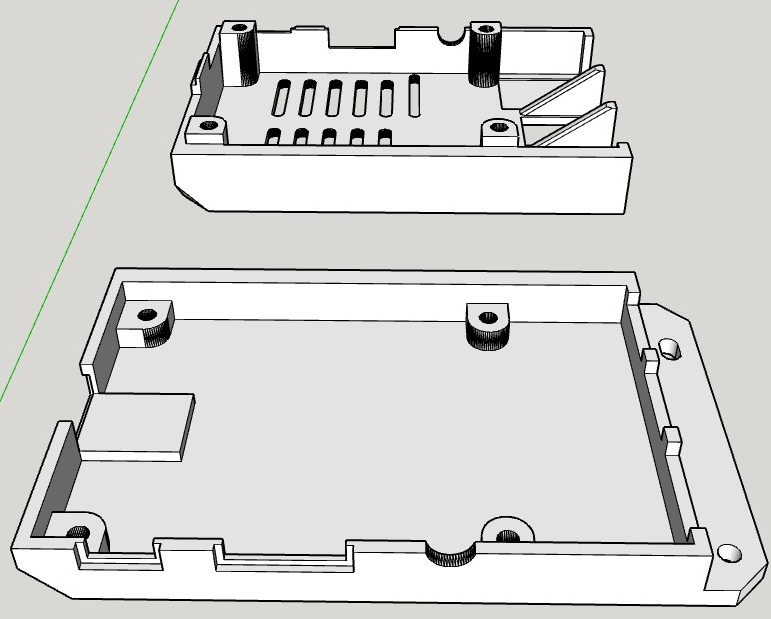
This is fixed on the back of the frame, in the upper left corner, using 2 x M3 screws. The upper part was modified to allow the access to the GPIO connector.
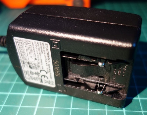
The original 5V/2.5A Raspberry Pi power supply was used.
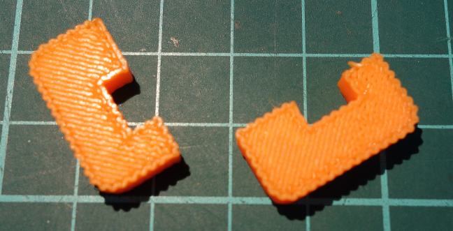
The power connector is modular, with adapters for different standards. The UK adapter was cut using a Dremel as in the following pictures.
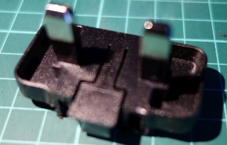
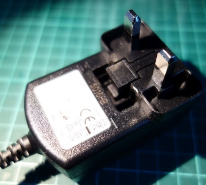
Glue the two 3D printed fillers to the power adapter.

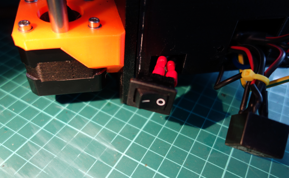
Two pieces of isolated wires will be soldered to the RPi PSU power adapter pins and then to the printer power connector. Use the 3D printed template to make 2 x 6 mm holes in the back of the black ABS box where the power switch and connector are placed. The RPi PSU must be permanently connected to the mains, no matter the position of the printer power switch.

A SPDT (or even SPST, normal open) relay is used to control the printer power. This will be wired as in the following picture:

One possible relay is the following ( http://www.ebay.co.uk/itm/281908114410 ):
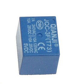
A bifilar piece of wire (~ 1m in lenght) will be soldered to the relay coil and then routed to the control module (described later). You can use any miniature relay with a 5V coil and able to swith 220V/3A.
The relay will be inserted in the same black ABS box under the printer PSU. When ready, slide the RPi PSU to the power connector.

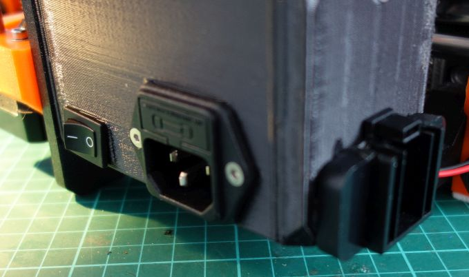
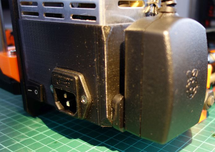
You will obtain at the end a clean look in the printer power supply area. The 5V cable from the RPi PSU will be routed to the control module (described in next chapter).
The control module will use two GPIO pins from RPi to control printer power (GPIO18) and light (GPIO23). The light will be automatically switched off when the printer is off. The schematic is presented in the following picture.
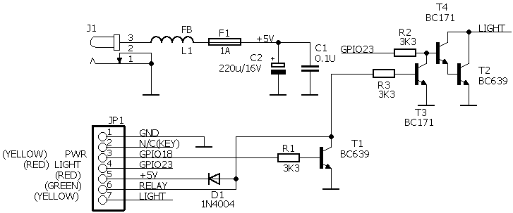
This is the bill of materials for this module.
Part Value Device Package Description
C1 0.1u C-EU050-024X044 C050-024X044 CAPACITOR, European symbol
C2 220u/16V CPOL-EUE5-8.5 E5-8,5 POLARIZED CAPACITOR, EU symbol
D1 1N4004 1N4004 DO41-10 DIODE
F1 1A TE5 TE5 Resettable FUSE, 1A
J1 JACK-PLUG0 SPC4077 DC POWER JACK
JP1 PINHD-1X7/90 1X07/90 PIN HEADER
L1 FB FB FB Ferrite bead
R1 3K3 R-EU_0204/7 0204/7 RESISTOR, European symbol
R2 3K3 R-EU_0204/7 0204/7 RESISTOR, European symbol
R3 3K3 R-EU_0204/7 0204/7 RESISTOR, European symbol
T1 BC639 BC639-NPN-TO92-ECB TO92-ECB NPN Transistror
T2 BC639 BC639-NPN-TO92-ECB TO92-ECB NPN Transistror
T3 BC171 NPN-TO92-EBC TO92-EBC NPN Transistror
T4 BC171 NPN-TO92-EBC TO92-EBC NPN Transistror
The PCB (single side) is presented in the following pictures. Eagle files are available by request.


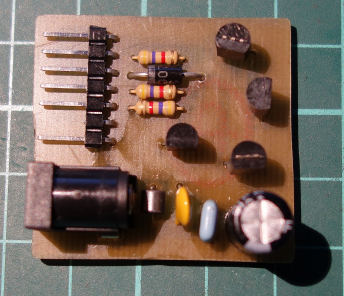
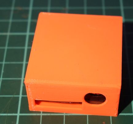
The PCB is mounted in a 3D printed case. Stick the case to the back of the printer frame (below the RPi) using double sided adhesive tape.

The RPi PSU 5V cable will be cut ~ 10cm from the microUSB connector and a 10cm of bifilar cable will be soldered with the DC power jack at the other end (used to power the control module).
A short cable will link one 7-pin female header (JP1 from the schematic above) to one 8-pin female header (pins 2-16 from the RPi GPIO connector).
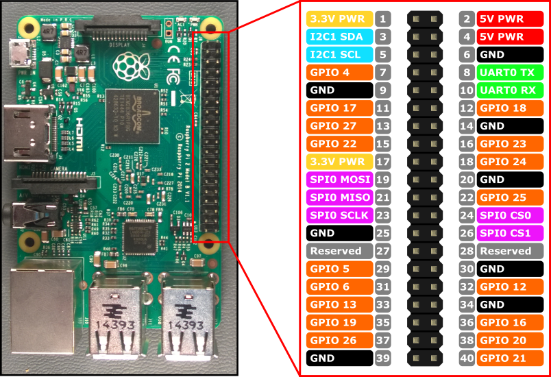
The 8-pin header will have the following connections (the numbers correspond to the RPi GPIO connector pinout:
(2) – +5V (JP1 pin 5)
(4) – Not connected
(6) – GND (RPi PSU and JP1 pin 1 )
(8) – Not connected
(10) – Not connected
(12) – GPIO 18 (JP1 pin 3)
(14) – Not connected
(16) – GPIO 23 (JP1 pin 4)
The 2 wires from the relay will be connected to JP1 pin 5 (+5V) and pin 6 (RELAY).
The two wires from the 5V LED light will be connected to JP1 pin 7 (LIGHT) and JP1 pin 1 (GND).
I’ve used a thin (3mm) coaxial cable to connect the LED light to the control module connector (+ for the central and GND for the braid). Considering the fact that the camera and the LED light are fixed to the printer bed, the cable to the LED light is routed together with the bed cables (heater and thermistor).
The 3D printed parts can be found here:
https://www.thingiverse.com/thing:2122419
This is how it looks with the RPi and control module fixed on the back of the printer frame.
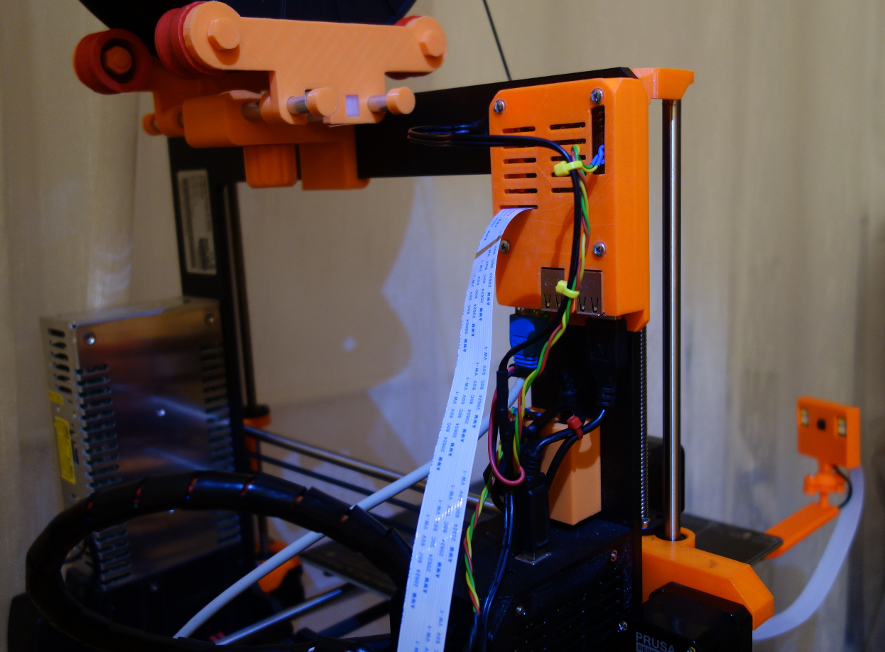
You can see in the picture the low profile adjustable spool holder too, available on Thingiverse here:
https://www.thingiverse.com/thing:2122419

A Raspberry Pi camera (V2.1 – 8MP) was used for this project.

Camera is connected to the RPi using a 1m flat cable, that can be ordered from here: (http://www.ebay.co.uk/itm/122640624047 ).

NOTE: Do not use longer cable to prevent unreliable camera connection. A shorter cable (60cm) will not be long enough for our purpose. 1m is just right.
All the camera related parts are available as STL files on Thingiverse here:
https://www.thingiverse.com/thing:2521717
You will need a fast and reliable microSD card (Class 10 as a minimum) to install the operating system and OctoPrint application. A 16GB or greater card is recommended as you will store some time-lapse video capture files (maybe even in 4K).
Follow the procedure described here:
https://www.raspberrypi.org/documentation/installation/installing-images/
No need to use NOOBS. Download the latest version of RASPBIAN STRETCH WITH DESKTOP from here:
https://www.raspberrypi.org/downloads/raspbian/
and write it to the SD card using Etcher.
For further steps I recommend you to connect a HDMI monitor and a USB keyboard to the Pi and a network cable to your router for Internet access.
As soon as the microSD card is prepared, insert it in the RPi and power it on. The OS will boot in graphical mode. Launch a terminal session and enter the following commands (check first that you have Internet access on your RPi):
sudo apt-get update
sudo apt-get upgrade
sudo reboot now
RPi will be restarted. Run the terminal and then enter the following command. In bold are the commands you send, the answer from the server is the rest.
ifconfig
Note the reported IP address. You will use it later to connect remotely through SSH or VNCviewer.
sudo raspi-config
You will be prompted with the following menu.
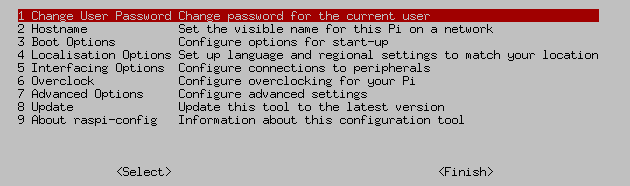
First thing to do is to change the user password. If you want to make available the printer over the Internet, use a long and difficult to guess password.
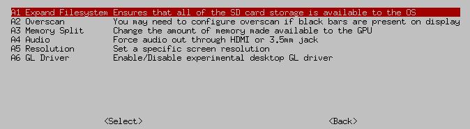
Use the “Interfacing Option” sub menu to activate the camera, SSH and VNC (can be useful later for management).

From the “Advanced Options” sub menu expand the filesystem, then exit the tool and restart the system.
From now on you can remotely connect to your Pi using SSH or a VNC viewer. Do not use TightVNC as this is not able to connect to RPi, use instead the free RealVNC viewer from here (select your preferred OS):
https://www.realvnc.com/en/connect/download/viewer/
Run VNCviewer on a PC connected to the same network. You will get the following interface.

Now you can configure the wireless interface and (optional) set static IP addresses.
Left click on the Wi-Fi symbol and select the wireless network you want to connect to. You will be prompted to enter the password for that network.

Enter the password and click OK. You will be connected to that wireless network.
Right click on the Wi-Fi symbol in the task bar and select “Wireless and Wired Network settings”
You will have two interface: LAN (named enxb….) and Wi-Fi (wlan0). Here you can configure static IP addresses if you want.
From a terminal session send the command:
ifconfig
and note the ip address for the wlan0 interface. This can be used later to connect to the printer over Wi-Fi.
Now is time to install and configure OctoPrint and webcam daemon. Follow the instructions presented here:
https://github.com/foosel/OctoPrint/wiki/Setup-on-a-Raspberry-Pi-running-Raspbian
When ready and OctoPrint is functional, open the file ~/.octoprint/config.yaml
Edit the “events” section as below. In order to prevent a bed mesh leveling calibration when the printer connects over USB, remove the G28 line from the ‘command’ subsection. Without this modification, if the print nozzle is not clear, the connection will fail because the nozzle is still cold and the printer will push the “dirty” nozzle to the bed.
events:
enabled: true
subscriptions:
- command: gpio write 4 1
event: PrintStarted
type: system
- command: gpio write 4 0
event: PrintDone
type: system
- command:
- M115
- M117 printer connected!
event: Connected
type: gcode
This will automatically start the light when print starts (if you forgot to start it manually).
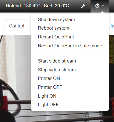
Edit “system” section as below:
system:
actions:
- action: streamon
command: /home/pi/ scripts/webcam start
confirm: false
name: Start video stream
- action: streamoff
command: /home/pi/scripts/webcam stop
confirm: false
name: Stop video stream
- action: prusaon
command: /usr/bin/gpio write 1 1
confirm: false
name: Printer ON
- action: prusaoff
command: /usr/bin/gpio write 1 0
confirm: false
name: Printer OFF
- action: lighton
command: /usr/bin/gpio write 4 1
confirm: false
name: Light ON
- action: lightoff
command: /usr/bin/gpio write 4 0
confirm: false
name: Light OFF
This section will add some direct commands in the OctoPrint menu.
In the /etc/rc.local file add the following two lines before ‘exit 0’ line, in order to automatically set the GPIO 4 and 1 as outputs during boot.
/usr/bin/gpio mode 1 out
/usr/bin/gpio mode 4 out
The printer is now ready to be used with the new features.
For any question related to this project please write me a mail.
INSTALLING OPERATING SYSTEM IMAGES https://www.raspberrypi.org/documentation/installation/installing-images/
Setup on a Raspberry Pi running Raspbian https://github.com/foosel/OctoPrint/wiki/Setup-on-a-Raspberry-Pi-running-Raspbian
Raspberry Pi 2 & 3 Pin Mappings https://developer.microsoft.com/en-us/windows/iot/docs/pinmappingsrpi
1.0 – first public version of the document
pimod_v1.0.pdf - Bucharest, Sep 9th 2017 – © Dan Toma – YO3GGX – yo3ggx@gmail.com