Dan Toma - YO3GGX - yo3ggx@gmail.com
This is an Android tool which allows you to configure devices over USB/Bluetooth/WiFi or to analyze the communication between two devices talking over different medium through a transparent mode.
Based on your feedback and suggestions, it will improve over time, so please be patient and confident that I will solve all the issues step by step. The application is and will remain free, but uses nonintrusive Ads displayed only when no connection established.
The idea of this application comes from a Windows application written by me many years ago, named SPCA (Serial Port Communication Analyzer) which is still available on my web site.
Current version of the application has the following features:
Can be used on any Android device, with OS version > 2.0 and resolution >= 320x480. It works even on smaller screens, but it can become unusable because of to small controls;
Possible to connect through Bluetooth (SPP profile), USB/Serial and Ethernet (TCP), both as client or server;
The USB/Serial devices based on the following chips are supported:
FTDI FT232R (0x0403:0x6001)
FTDI FT230X (0x0403 :0x6015)
SILAB CP210x (0x10C4: 0xEA60)
Prolific PL2303 (0x067B: 0x2303)
You can use the application in client, server or transparent mode. In transparent mode you can transfer and monitor the data between different type of devices, as follows:
Integrated 30 keys keypad which has a reserved space on the screen;
Keypad can be used in different mode: letters (both smalls a caps), numbers (including hex and bin), symbols and Memory (Macro);
All data to be sent is octet (byte) based and can be entered as char or by code (0-255) in decimal, hex or binary;
Display the number of bytes to be send available in the buffer, including the string representation of them ( in UTF-8);
The byte array is send only when you press enter key;
You have the possibility to select the option to automatically add at the end of the buffer “classic” control characters: CR(code 13) and/or LF(code 10);
26 Memory locations where you can save some pre-defined byte arrays (no size limit) which then can be added by a single click. For each macro you can specify the number of times to repeat the sequence between 1 and 999999. The macros are automatically saved in the application configuration file;
Large frame to display returned data (capacity dependent on font size);
You can display returned data as one, two, four, eight or an unlimited number of values per row;
Data can be displayed in different formats: char, binary, decimal or hex);
Data can be considered per 8, 16, 32 or 64 bit;
You can select between Little and Big Endian conventions for data longer than 8 bit;
The total number of bytes in the receive buffer is displayed as a decimal value;
Bluetooth pairing can be done inside the application if not done before;
You can see name and MAC address for the local and remote Bluetooth device;
You can see local IP address (useful when you initiate network in server mode;
Remote host can be entered from the keypad as hostname or IP address;
Local and remote ports can be entered through the numeric keypad;
Operation mode is selected through a single button;
SET button to save the settings;
You are prompted to automatically launch the application when a supported USB/Serial interface is connected;
Connection status displayed by colorful symbols on the screen (Blue for Bluetooth, Magenta for USB, Green for TCP/IP);
Automatically adjust font size based on device and system font size. A manual mode is available too, through an intuitive graphical interface;
Current version of the application has the following limitations:
Application can be used only in Landscape mode;
WARNING!!!
Use this application on your own risk. I cannot be held responsible for any damage caused to your Android device.
Download and install current version of the application from Google Play Store. Search for the name “NSCOM” or use the link from the top of this doc.
Run the application (named NSCOM) with the icon below:

If you start the application for the first time or after a configuration file reset, you will get the following startup page:
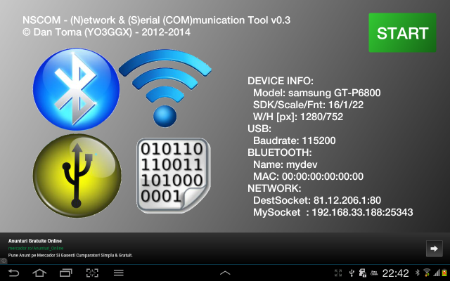
On the startup page you can see some information about:
Your android device (manufacturer, model, OS version, resolution);
Current font size (can be changed inside the application);
USB/Serial Baudrate;
Remote Bluetooth device name and MAC address;
Destination network socket (for Network Client mode);
Local network socket (for Network Server mode);
If for some reason you want to reset the entire configuration file (if for example gets corrupted), you just have to long press on the START button. You will be asked for confirmation.
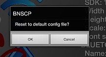
Press “OK” if you want the configuration file to be reset, or “Cancel” if not.
To start using the application just press “START” button.
After you pressed START button you must see a screen similar with the following (based on the operation mode):
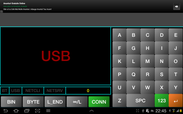
Client or Server Mode when not connected Transparent mode when not connected
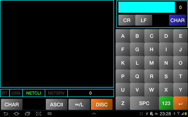
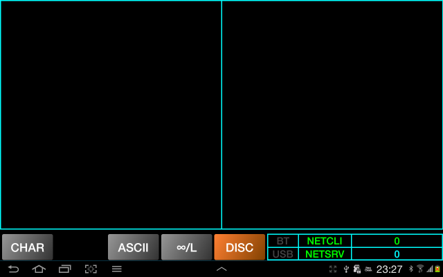
Client or Server Mode when connected Transparent mode when connected
If you have issues related to the application fonts (too big or too small) go directly to the chapter explaining how to change font size here.
One or two big panes are used to display received/transmitted data. Received data is displayed in Green, sent data in Cyan. The same colors are used to display the number of bytes received/sent. Each type of connection is represented by the following symbols – colors. When that specific connection is not active, the symbol is grayed.
BT - Bluetooth – Blue;
USB – USB/Serial – Magenta;
NETCLI – Network Client – Green;
NETSRV – Network Server – Green.
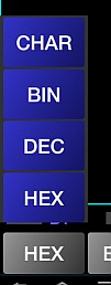
Four gray buttons are used to select the way received data is displayed. By clicking on any of them several new buttons will pop-up, as follows:
First button – Format: hex (8-32 bit), signed decimal (8-32 bit), binary (8-32 bit) or char (8-16 bit);
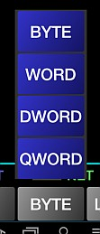
Second Button – number of bits per received value (8 - byte, 16 - word, 32 – double word, 64 quad word);
Third button has different functions for char mode or other modes. In char mode you can select between UTF-8, ASCII or UNICODE convention, for the other between little or big endian convention;
![]()
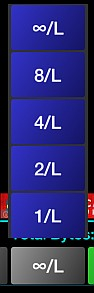
Fourth button allows you to select how many values you want to be displayed per row, between 1, 2, 4, 8 or unlimited;
The green button has multiple functions and can have one of the following labels: “CONN/WAIT/DISC”
The actions are described in the following table.
|
Label |
Click |
Long Click |
|
CONN |
Connect |
Clear data from all available panes |
|
WAIT |
Do nothing |
Cancel connecting |
|
DISC |
Disconnect |
Clear data from all available panes |
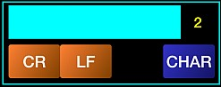
A box in the upper right corner of the screen (available only when connected) will display the data entered by the user, will allows you to change between char and code mode and to opt for adding CR and/or LF characters at the end of the entered data.
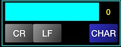
When CR and/or LF are selected, button color will change to orange.
The cyan field is used to display the data buffer prepared to be send over Bluetooth / USB-Serial or Ethernet.
You can shortly press on that field to erase the last entered char/byte or long press to clear the full field and reset the buffer.
In the right part of this field the number of the bytes from the send buffer is displayed as a decimal value. If CR and/or LF characters are selected, then the number will be incremented accordingly.
A blue button is used to switch between Char and Code modes. In Char mode, any character entered from the keypad will be added to the buffer as his byte value (in UTF-8). In Code mode, the button caption will change to “CODE” and you have to enter the value of that byte. The cyan field will contain the text “Code:” waiting for your input.
You can use decimal value, hex value (using ‘0x’ prefix) or binary value (using ‘1x’ prefix). Entered value must not be less than -128 or greater than 127 (decimal). The application accepts both signed and unsigned values.
Some valid examples below:
|
Decimal |
Hex |
Binary |
|
|
|
|
The keypad is presented in the following chapter.
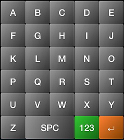
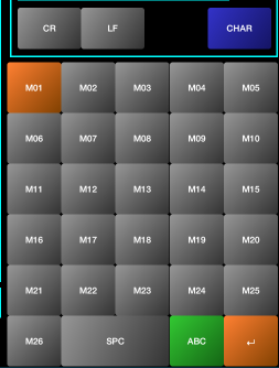
The keypad is composed of 30 keys and you can select between 4 possible layouts.
A green button is used to change between the layouts (caption changes together with the layout for the next available one).
For some specific functions (like code entering) the layout is selected automatically and the options to change restricted.
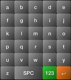
First is the letters layout (in both capitals and small). To toggle between then, long press on any letter. Long press on SPC (Space) key to generate a dot. This can be useful to enter hostnames. The orange key in the lower tight part of the keyboard is the ENTER key. This one, together with SPC key are common for all the layouts. When in Char entering mode, pressing ENTER key will send the data from the buffer and will clear the buffer and enter field. When in Code entering mode, load current displayed code as a byte and add it to the buffer.
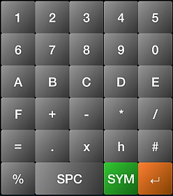
Pressing the green ‘123’ button the keypad layout will switch to numbers. This one contain some characters which can be useful to enter hex digits (A-F), arithmetic operations (+, -, *, /,=) or hex/binary values (‘x’).
Pressing the green SYM key the layout will change to symbols. There are no special functions for this layout.
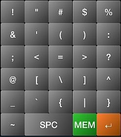
Pressing the green MEM key the layout will switch to Memories (MACROS).
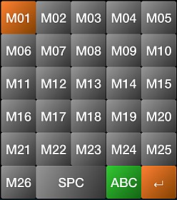
You have 26 memory locations available to save group of bytes which you need to send most often.
The memory keys color is gray when no data is stored at that position and goes orange when minimum one byte was saved at that position. To save first enter the char/bytes you want and then long press on a free memory button.
You will be asked for how many times you want to repeat that sequence (between 1 and 999999).
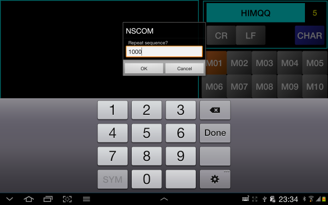
If that memory was not empty, the new value will overwrite the previous one. All memories data is saved in the configuration file for further use.
To load a specific set of bytes from the memory, just short press on that memory and containing data will be appended to the existing send buffer and length value incremented accordingly.
Use this procedure only if you are not satisfied with the automatically set font size.
Select from the application menu “FONTSIZE”.
![]()
The current font size and height is displayed with black on a cyan background, inside the received data frame.
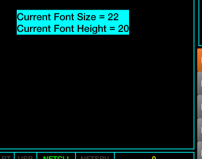
Slide one finger vertically over the black background of the frame, up to increase or down to decrease font size. The background will go gray and all the fonts on the screen will change to the new value. Below you can see two examples with small and very big fonts (keypad section only).
NOTE: When the font is too big, some fields from the screen may be wrapped. You can return to the procedure at any time and decrease the font size. The maximum font size is limited in the application to 32.
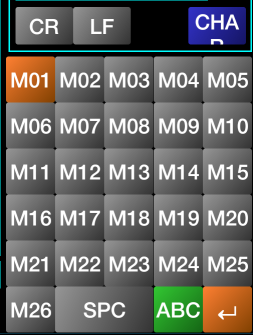
The minimum value is limited to 3. The absolute value for font size depends on the device type, Android version and system font size.
When you are satisfied with the aspect, slide one finger horizontally to save the new font size value in the configuration file and to return from this mode through a small animation.
To set the operation mode select “SETUP” from the application menu or click on the zone with the symbols representing the connection types (in both transparent and non-transparent modes). The screen will change like in the following picture.
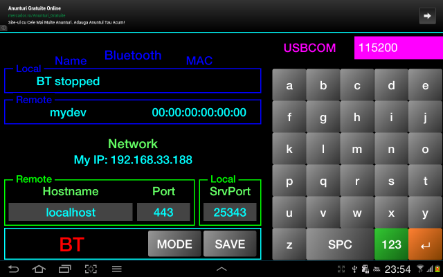
In the upper part you can see the name and MAC address of the local Bluetooth device plus the name and MAC address of the remote device (only if a connection was previously established and data saved). These fields are not editable.
In the middle you can see your own IP address, which must be used if you use Network Server mode. Below that, 3 editable fields are used for:
Hostname (or IP address) of the server to connect to in Network Client mode;
Port number (TCP) to connect to;
Local port used for server mode.
To edit any of these fields just short press on it and the background will change to cyan.
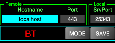
Use the keypad to enter the name or the IP address. To delete the last char, short press the cyan field. To completely delete the whole field, long press on it. The same procedure applies for the other two fields.
Use MODE button to toggle between the available modes. See here for the full list.
In the upper right corner there is a dropdown list of possible Baudrates to choose from for the USB/Serial connection. Click on the Magenta field to display the full list.
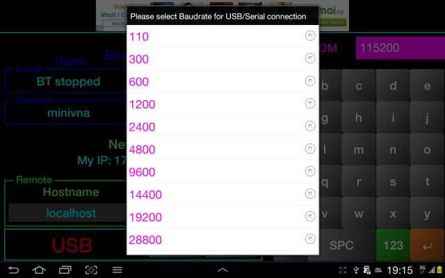
You can choose between the following values: 110, 300, 600, 1200, 2400, 4800, 9600, 14400, 19200, 28800, 38400, 57600,115200,230400, 460800 and 921600. Please check supported values for your specific interface.
When all the parameters are set, click on SAVE to save them in the configuration file.
If you want to cancel and to return to the main screen, long click on the SAVE button.
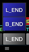
When you select a specific mode, the mode label is displayed on the left pane with big red letters. This label disappear when the connection is established.
After you set Bluetooth mode as described in the previous chapter, click on CONN button to initiate Bluetooth connection. If this is for the second time, the connection will be established automatically. If for the first time, you will be prompted to select the device you want to connect to. The list will contain all the Bluetooth devices in the range which are discoverable and supports Serial Port Profile.
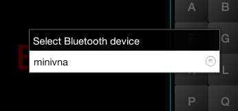
Select the device you want to connect to. Only if the device was never connected before, you will be asked for the pairing PIN. Enter it and click “OK”
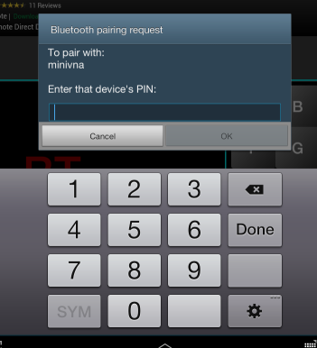
The BT Symbol will go blue if the connection was successful and the Ad on top of the page will disappear.
![]()
You are now ready to send and receive data to/from that device. See the other chapters to learn how to enter data and to select output format.
To use USB serial mode, you need to connect the USB/Serial interface before starting the application. You will be asked to automatically start the application.
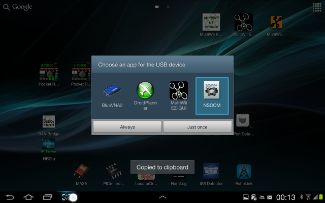
Select “Just once” if you have other applications available too. The USB symbol will go Magenta if the connection was successful and the Ad on top of the page will disappear.
![]()
NOTE: If you disconnect a mode using USB, you will need to restart application in order to be able to reconnect the USB. This is a known bug in Android.
After you set NETCLI mode as described in the chapter “Setting the operation mode”, click on the green CONN button to initiate network connection to the server/port specified in the setup window. If the connection is successfully established, the NETCLI symbol will go green and the Ad on top of the page will disappear.
![]()
You are now ready to send and receive data to/from that device. See the other chapters to learn how to enter data and to select output format.
After you set NETSRV mode as described in the chapter “Setting the operation mode”, click on the green CONN button to start listening on the port configured in the setup window. You will be prompted to connect to the specified IP:port (local host IP). The NET SRV symbol will go orange to show you that the server is listening for external connections.
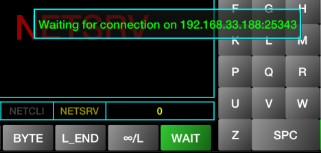
You can now connect from the remote client to the local server. When the connection is established, the NETSRV symbol will go green and the Ad on top of the page will disappear.
![]()
You are now ready to send and receive data to/from that device. See the other chapters to learn how to enter data and to select output format.
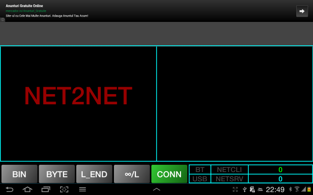
You can choose between several available transparent modes which are just combinations between two basic operation modes. The full list is the following:
NET2NET – between Net Client and Net Server;
BT2USB – between Bluetooth and USB/Serial;
BT2NETCLI – between Bluetooth and Network Client;
BT2NETSRV – between Bluetooth and Network Server;
USB2NETCLI – between USB/Serial and Network Client;
USB2NETSRV – between USB/Serial and Network Server.
In each of those modes, you will not be able to send commands, but just to monitor the traffic between the two devices. Each direction data is displayed in the corresponding panel.
After you set NETSRV mode as described in the chapter “Setting the operation mode”, click on the green CONN button to start both connections. Only when both of the connections will be established the green button will change from “WAIT” to “DISC”. The number of bytes will be displayed with the color used for each pane (left – green, right – cyan). You can find an example below for a command send (in the right pane, cyan) and the answer (in the left pane, green), , in NET2NET mode different display modes.
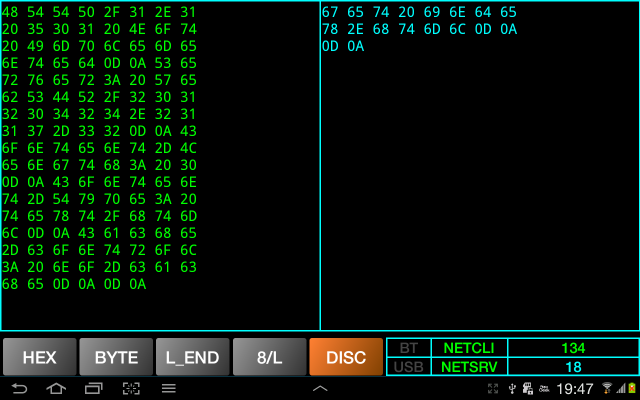
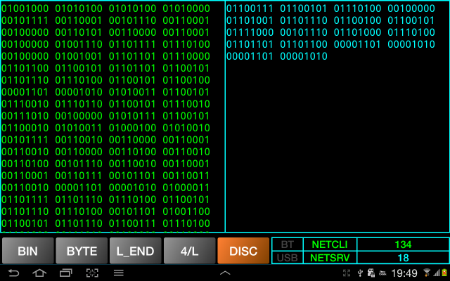
Hexadecimal, 8 bytes per row Binary, 4 bytes per row
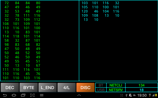
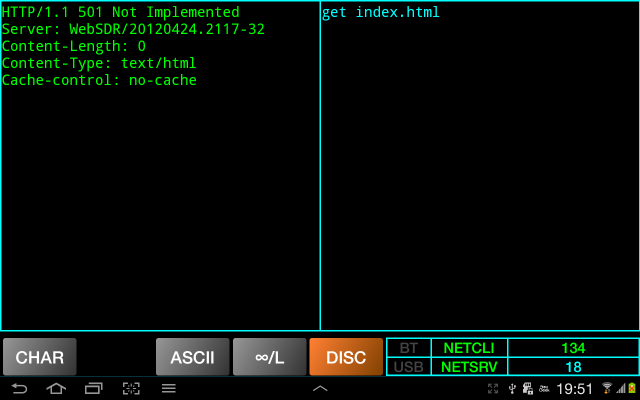
Decimal, 4 bytes per row Characters, ASCII, no line separation
You can see a short demo of the operation on YouTube: http://www.youtube.com/watch?v=Itqe7Hl06_E
Other demo videos will be added in the future, so you can subscribe to YO3GGX channel if you want to be informed in real time.
Please send me your feedback. Further development of the application fully depends on YOU.
Android SDK documentation : http://developer.android.com/sdk/index.html
USB/Serial library for Android: https://code.google.com/p/usb-serial-for-android
Version 0.1 (Dec 8th, 2012). Initial version of the application (v0.1)
Version 0.3 (Jan 28th, 2014).
rewritten engine;
changes in the GUI;
add USB/Serial support for PL2303, FT232, FT230x, CP2102 based USB/Serial interfaces;
added combined combined transparent modes;
better handling for the font size. Now the default font size is automatically calculated and set based on device resolution, size and dpi. You can still change it manually if you want;
new application name - NSCOM, new icon and new startup page picture;
nscom_v0.3.pdf Bucharest, Jan 28th 2014 – © Dan Toma – YO3GGX – yo3ggx@gmail.com