Dimmable 5V LED desk lamp
A dimmable desk lamp that can be powered from any 5V/1A DC source
Version 1.0
Dan - YO3GGX - yo3ggx@gmail.com
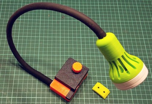
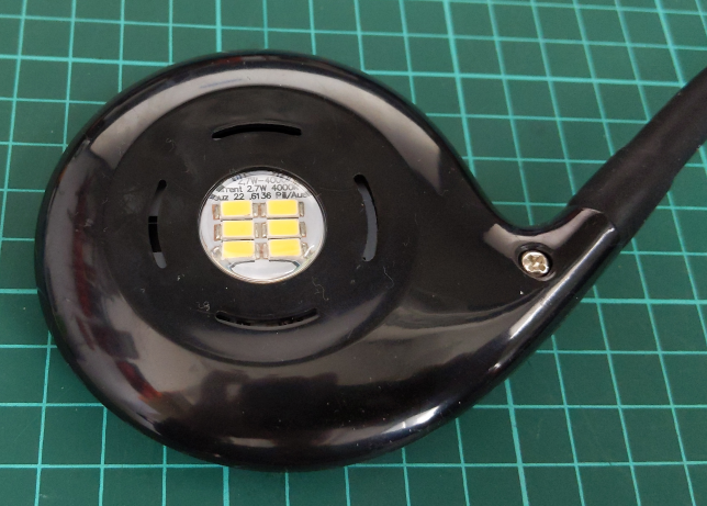
This a LED desk lamp that can be easily mounted in any position using a removable mount and powered for any 5V/1A power supply, even from a power bank. The light can be controlled from a rotary encoder and has soft-on soft-off capabilities.
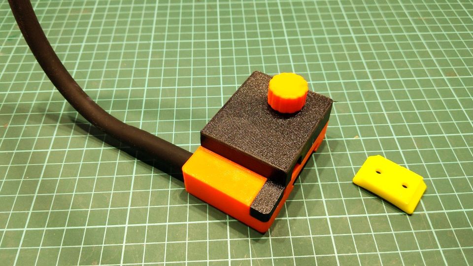
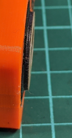
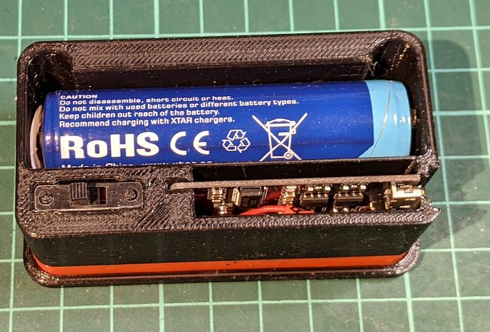
The final products look like in the following pictures.
Schematic is presented
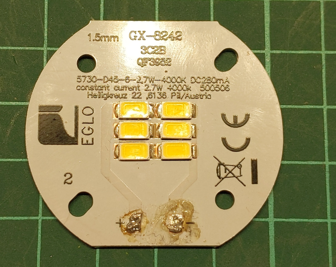
in the following picture. The used LEDs module is designed for 280mA
at a voltage around 9.5V.
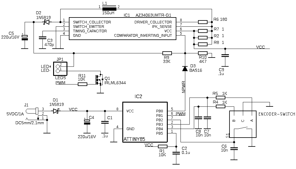
To power the LEDs module, a step-up voltage converter built around IC1 is used. The schematic is based on the IC datasheet. The current limit is established through R2-R7-R8 (3 resistors in parallel for a higher power). Output voltage is set through the R9/R10 divider, calculated in order to get 1.25V on the IC1 pin 5 for the desired output voltage. You can modify the resistors to match your specific LEDs module.
To set the dim level and on/off status a rotary encoder is used, controlling an ATTINYT85 that generates the PWM signal.
D3 allows the DC-DC step-up converter to be switched off when light is off, to significantly reduce current consumption.
This is the complete list of parts (BOM):
Part Value Description
R1,R11 10K 1206 SMD resistor
R2,R7,R8 1 1206 SMD resistor
R4,R5 1K 1206 SMD resistor
R6 180 1206 SMD resistor
R9 33K 1206 SMD resistor
R10 4K7 1206 SMD resistor
C1,C2,C9 .1u 1206 SMD capacitor
C3 470p 1206 SMD capacitor
C4,C5 220u/16V Electrolytic capacitor
C6,C7,C8 10n 1206 SMD capacitor
D1,D2 1N5819 1.0A SCHOTTKY BARRIER RECTIFIER (DO-41 case)
D3 BAS16 DIODE (SOT23 case)
IC1 AZ34063UMTR-G1 1.5A Step-Down/Up DC-DC Converter (SOIC-8 case)
IC2 ATTINY85 8-bit Microcontroller (SOIC-8 case)
J1 DC5mm/2.1mm DC POWER JACK
JP1 LEDS module LED module 280mA/10V
L1 150uH DR127 High Power Density, High Efficiency, Shielded Inductor
Q1 IRLML6344 30V Single N-Channel HEXFET Power MOSFET (5A, SOT-23 case)
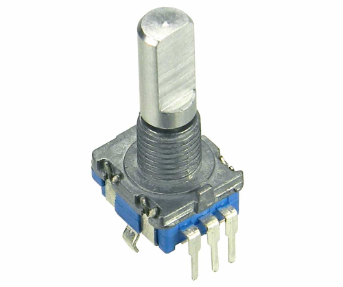
S1 Rotary Encoder w/ Select Switch
Let’s now see where we can find the main components from a trusted source.
1206 SMD capacitors (~ $14/pcs.) at:
https://uk.farnell.com/w/c/passive-components/capacitors/ceramic-capacitors/smd-ceramic-multilayer-mlcc-capacitors?voltage-rating=50v&ceramic-capacitor-case=1206-3216-metric-&packaging=cuttape&range=inc-in-stock|exc-delivery-surcharge&sort=P_PRICE
![]()
1206 SMD resistors (~.1c/pcs.) at:
![]()
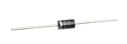
1N5819 Schottky Rectifier, 40 V, 1 A, Single, DO-41 (DO-204AL), 2 Pins, 900 mV (~ 5c/pcs.) at:
https://uk.farnell.com/multicomp/1n5819/schottky-rectifier-1a-40v-do-204al/dp/2675095?st=1n5819
BAS16 – General purpose Switching Diode (~ 5c/pcs.) at:
![]()
AZ34063UMTR-G1 - 1.5A STEP-DOWN/STEP-UP/INVERTING DC-DC CONVERTER (~ 5c/pcs.) at:
![]()
ATTINY85 - 8 Bit MCU, AVR Series Microcontrollers, 10 MHz, 8 KB, 500 Byte (~ $1/pcs.) at:
![]()
LEDS module – obtained from an EGLO Japura LED lamp, together with the goose neck (~ 1/pcs.) at:
https://www.decorino.ro/lampa-birou-japura-led-2-7w

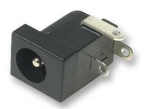
DC 5mm/2.1mm power connector (~50c/pcs.) at:
https://www.conexelectronic.ro/ro/conectori-dc/4716-PRIZA-DC-2-1-MM-PANOU-PLASTIC.html
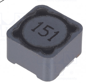
PCS127MT151 - SMD; 150uH; 1,42A; 280mΩ; 12x12x8mm (~50c/pcs.) at:
https://www.conexelectronic.ro/ro/conectori-dc/4716-PRIZA-DC-2-1-MM-PANOU-PLASTIC.html
IRLML6344TRPBF - Power MOSFET, N Channel, 30 V, 5 A, 0.022 ohm, SOT-23 (~30c/pcs.) at:
https://www.conexelectronic.ro/ro/conectori-dc/4716-PRIZA-DC-2-1-MM-PANOU-PLASTIC.html
![]()
PEC11R-4215F-S0024 - Incremental Rotary Encoder, 24 Detents, 24 Pulses, Quadrature Output (~$1.2/pcs.) at:
https://ro.farnell.com/bourns/pec11r-4215f-s0024/incremental-encoder-2ch-24pulse/dp/2474844
A single side PCB is used. SMD components are mounted on the back of the PCB.
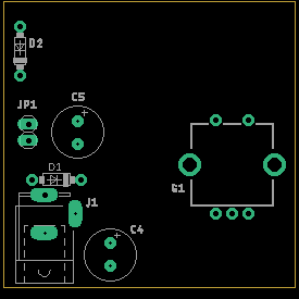
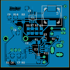
Eagle files are available by request.
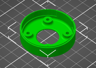
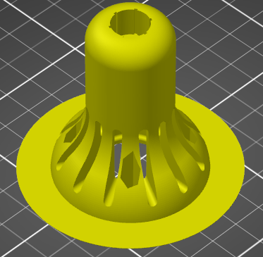
You can easily 3d print the case, the actuators mounting template and the protection cap.
|
Lamp front |
|
|
Case main body |
|
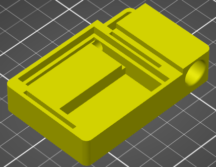
|
Case bottom |
|
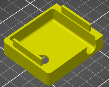
|
Case top |
|
|
|
|
|
Case small top |
|
|
|
|
|
Button |
|
The STL files can be downloaded from here: https://www.yo3ggx.ro/leddesklamp/case.zip
Glue the two exciters to the case bottom. Use the exciters mounting template to keep the exciters ~ 1.5mm outside the case, in order to provide enough space to vibrate. You may need to trim the contacts of the exciter. Take care not to cut the thin wires.
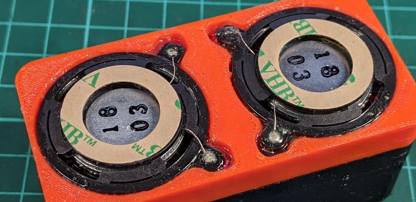
Solder 4 piece of 30AWG wires (~8cm in length) to the exciters and pass two of them through the hole in the case bottom, in order to have all of them on the BT module side. Solder the wires to the BT module (L+, L-, R+, R-). Connect the + of the Li-Ion battery to the SW1 switch. Connect the other contact of the SW1 switch to the VBAT contact of the BT module. Connect the – of the Li-Ion battery to the GND contact of the BT module. This is all.
Before mounting the top of the case, let’s do a test. Put the switch in ON position. The blue LED on the BT module will start blinking. From a smartphone search for a Bluetooth device named MH-M38 and do the pairing. Check that you can play from the smartphone to the BT audio exciter. If everything is ok, you can mount the case top.
NOTE: There is no need to glue case parts.
Short video with the device in action:
M38 module datasheet: https://www.sunrom.com/get/996418
DAEX19SL-4 datasheet: https://www.parts-express.com/pedocs/specs/295-261--dayton-audio-daex19sl-4-specifications.pdf
This is the software that you must program in the ATTINY using your preferred method. Copy and paste the code in Arduino IDE.
#include "avr/interrupt.h"
/*
ATTiny 85 LED dimmer with rotary encoder and soft-start / soft-stop
Dan Toma (YPO3GGX) - Mar 14, 2020
pin port usage
2 PB3 Channel B
3 PB4 Channel A
5 PB0 Light On/Off output
6 PB1 LED PWM output
7 PB2 On/Off button
*/
#define LED PB1 // pin 5
#define BUTTON PB2 // pin 7
#define ENCA PB4 // pin 3
#define ENCB PB3 // pin 2
#define POWER PB0 // pin 6
#define ON 1
#define OFF 0
#define MINVALUE 10 // minimum light intensity when on
volatile int stat = OFF; // light status OFF at power up
bool previousB = false;
int stp = 4; // increment/decrement for brightness (64 steps)
volatile int portReading = 0;
volatile int value = 255; // dimmer value, between 0 and 255
volatile int updated = 0; // 0 - no update, 1 - BUTTON pressed, 2 - rotated
bool maxpulse = false; // if true, a short pulse when level at max, oly one time
void setup() {
pinMode(BUTTON, INPUT_PULLUP); // Pull up reduces need for external resistor
pinMode(POWER, OUTPUT); // light power ON/OFF
pinMode(LED, OUTPUT); // PWM LED output
pinMode(ENCA, INPUT_PULLUP); // Inputs for rotary encoder
pinMode(ENCB, INPUT_PULLUP);
analogWrite(LED, value); // LED off when power on
digitalWrite(POWER, ON);
GIMSK |= (1 << PCIE); // Enable PCINT interrupt in the general interrupt mask
//GIMSK = 0b00100000; //turn on pin change
PCMSK |= (1 << ENCA) | (1 << ENCB) | (1 << BUTTON); // Set ENCA, ENCB and BUTTON as interrups
//PCMSK = 0b00011000; // turn on interrupts for pin 2 (PB3) and 3 (PB4)
sei(); //turn interrupts on
}
void loop() {
if (updated == 1) { // button pressed (soft start/stop)
updated = 0;
if (stat == ON) {
digitalWrite(POWER, OFF);
for (int i = 0; i <= value; i++) { // soft start
analogWrite(LED, i);
delay(4);
}
} else {
for (int i = value; i >= 0; i--) { // soft stop
analogWrite(LED, i);
delay(4);
}
digitalWrite(POWER, ON);
}
} else if (updated == 2) { // rotation up/down
updated = 0;
if (stat == OFF)
return;
else if (value < MINVALUE)
value = MINVALUE;
else if (value > 255)
value = 255;
if ((value == 255) & maxpulse) {
maxpulse = false;
digitalWrite(LED, OFF); // send a short blank (first time only) to know that the brightness is at maximum
delay(100);
}
analogWrite(LED, value); // set PWM factor
}
}
/* Pin change interrupt vector */
ISR (PCINT0_vect) {
//read the port quickly, masking out other pins
portReading = PINB & 28; // ENCA, ENCB and BUTTON (bits 4,3,2)
// read button
if (updated != 0)
return;
if ((portReading & (1 << BUTTON)) == 0) { // button pressed
if (stat == OFF) {
stat = ON;
} else {
stat = OFF;
}
updated = 1;
} else if (stat == OFF) { // do not deal with the knob is in OFF state
updated = 0;
return;
} else if ((portReading & (1 << ENCA)) == 0) { //read channel A
updated = 2;
//determine what part of the waveform we are on
if (previousB) {
value -= stp;
maxpulse = true;
} else {
value += stp;
}
}
//record b channel for use next time round
previousB = (portReading & (1 << ENCB)) == 0;
}
ATTINY datasheet http://ww1.microchip.com/downloads/en/DeviceDoc/Atmel-2586-AVR-8-bit-Microcontroller-ATtiny25-ATtiny45-ATtiny85_Datasheet-Summary.pdf
AZ34063U Datasheet https://www.diodes.com/assets/Datasheets/AZ34063U.pdf
Rotary Encoder Datasheet http://www.farnell.com/datasheets/2360546.pdf
Initial version of the document (v1.0).
LED_desk_lamp_v1.0_EN.pdf Bucharest, Mar 14th 2020 © Dan Toma – YO3GGX – yo3ggx@gmail.com