 jAReC5
(j)ava (A)udio and (Re)mote (C)ontrol
A Java multiplatform application used to remote control your transceiver locally (over serial/USB/Bluetooth) or over the network.
Version 5.0 beta
Dan Toma - YO3GGX - yo3ggx@gmail.com
Contents
Application folders and file structure’s
Creating a new application profile
Using Audio spectrum, audio DSP and app Squelch
Audio Spectrum Window in Rx mode
Audio Spectrum Window in Tx mode
Adjusting Low Pass Filter (LPF)
Adjusting Band Pass Filter (BPF)
Waterfall with internal jAReC5 SDR engine
Waterfall with supported radios from iCOM
Tunning the radio using the waterfall
Using jAReC5 with a (tr)uSDX radio
(tr)uSDX radio in Direct Control mode
Current Limitations for (tr)uSDX radio operation through jAReC5
Using jAReC5 with a RTLSDR/RSP1A dongle
Installing rtl_tcp server on a Windows computer
Installing rtl_tcp server on a Linux (Debian flavor) computer
Installing rtl_tcp server on a Mac computer
Installing rsp_tcp server on a Windows computer
Installing rsp_tcp server on a Linux (Debian flavor) computer (RSP-1A only)
Installing rsp_tcp server on a Linux (Debian flavor) computer (non RSP-1A)
Installing rsp_tcp server on a Mac computer
Configure jAReC5 to connect to the rtl_tcp/rsp_tcp server
Using jAReC5 with a radio with IQ output (Malahit DSPx)
Displaying data received from the radio
Commands definition syntax (TAGs)
Patterns definition syntax (TAGs)
Program history (staring with first v5 beta)
V5.0 beta1 – first public beta release (Jul 30, 2023) – version code 4.99.11
Introduction
This is a multi-platform Java application which can be used to control your own CAT enabled transceiver (with audio support) using a Serial/USB Serial/Bluetooth or network connection. jAReC can act as both a server and as a client. The PocketRxTx Android application can be used as a client securely to connect over the network and control (CAT) your radio transceiver remotely via jAReC server over the Internet or local LAN, with bi-directional audio support.
Features
The current version of the application has the following features:
New in v5 (from v4.x):
· Full SDR functionality for Rx, supporting RTL/RSP dongles over rtl_tcp, IQ based receivers (Malahit DSPx, Softrock, etc.), local and remote (over HTTPS) IQ wave files.
· LSB, USB, CW, AM and FM decoding for IQ signals.
· Redesigned spectrum and waterfall display for SDR, with touch to tune functionalities.
· Audio spectrum display.
· Audio DSP for both Rx and Tx, with user configurable low pass, band pass and notch filters (Rx) or band pass and adjustable compander (Tx). This feature is available for any radio.
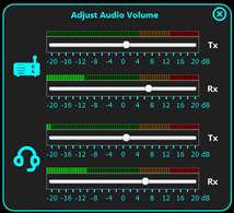
· Audio volume adjustment for both input and output audio channels, with level meter for each of them.
· Full support for (tr)uSDX, including audio over CAT (both Rx and Tx).
· Audio, waterfall and CAT over the same TCP port (UDP no more used) in client-server mode.
· Variable bitrate Opus codec is now used instead of uLaw in client-server mode, for lower bandwidth.
· Possibility to record (in a wave file) received audio, after DSP.
· Only the first 6 defined parameters are displayed in the main radio window, all the others are available through a separate parameters panel.
· All radio configuration files are embedded in the application, for the situations when the central server is not available.
· Bridge and SRV v3 modes removed.
· Redesigned (simplified) GUI for the startup page and radio.
· App folders structure changed
Other features (inherited from previous version):
· Can be run on Windows, Linux, or Mac.
· The application is self-contained and fully portable. It can even be run from a memory stick. Nothing is modified in the hosting operating system.
· You do not require to install a java runtime environment.
· Several configuration profiles can be set within jAReC. One for each mode of operation (direct control, client, or server mode) or for multiple transceivers connected at different times to the same computer where jAReC is installed. You can just load the saved profile you wish without having to reconfigure the application each time you change the operational mode or transceiver.
· Waterfall support added for Icom IC7300 and IC705 (limitations: when waterfall active, only FREQ, MODE and FLT are updated in the GUI when changed directly on the radio).
· Auto info support added (for the transceivers that can auto transmit parameter value when changed. For CI-V only FREQ, MODE and FLT are transmitted, for some Yaesu models (ex. FT450) all parameters value are automatically returned when changed directly on the radio (including meters), so continuous polling is no more required.
· You can select any local serial port (COMx in Windows, /dev/ttySx or /dev/ttyUSBx in Linux, etc).
· Serial ports can be named, so you can easily identify them afterwards.
· You can select Audio In and Audio Out devices from a list.
· Two audio interfaces can be defined in direct control mode: one for radio audio and the other one for a local wired or wireless headset.
· The TCP port used for the remote connection is configurable.
· The Baud rate is configurable from 110 to 921600.
· Settings are saved in a configuration file and are loaded automatically the next time the program is started.
· The program can be automatically started allowing unattended mode operation.
· In server mode, the program auto disconnects if the network link is lost and goes back to “waiting for connection” status, without user intervention.
· When jAReC is being used to control a transceiver, PTT control can be done over CAT or through RTS or DTR signals, on the same serial port used for CAT controls or on a different one.
· There is a user configurable PTT timeout setting, to prevent PTT locking in Tx if the network link drops during transmission.
· Custom commands/scripts can be sent as CAT commands.
· A graphical configuration builder is included. This includes the facility to test different/modified CAT commands and then to create or edit a radio configuration file according to your own needs.
· The application includes call logging features, with QRZ.com integration for automatic filling of station details by querying the QRZ.com database. You need a valid free QRZ account for basic information (Name, QTH, Country), or a paid XML subscription to get all available information for the station being entered in the log.
· A CW Keyer is included, allowing you to send pre-entered CW messages. The speed is user adjustable. Up to 8 messages can be pre-defined.
· Internal and external tuners are supported, making the antenna tuning process much simpler. When triggered the desired TX mode and level is used for the tuning action.
· You can display the SWR graph across the currently selected band in up to 100 steps.
· Auto transceiver power on/off when connecting to the radio from jAReC (user selectable).
· Full support for Contour Design ShuttleXpress (without requiring extra drivers). You can control almost all radio functions through this device.
· Keyboard shortcuts are present for some of the main functions.
IMPORTANT!!!: jAReC5 is no more compatible with Pocket RxTx v3.x. Until Pocket RxTx5 will be released, use jAReC v4.x with Pocket RxTx v3.x.
WARNING!!!
Use this application at your own risk. I cannot be held responsible for any damage caused to your system or transceiver by using this application.
Application folders and file structure’s
The application folder is the one from where the application is started. For the packaged versions this is the executable folder (bin subfolder). When you run the jar file directly through a script, it is the script folder.
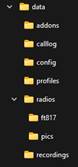
The app folder structure is the following:
|
|
è Subfolder of the folder from where the app is started è Addons folder (used for RTLSDR, etc) è ADIF CallLog files (.adi) è jsn4.cfg(jAReC config file) è *.prf4 (profile files) è *.radio4 (radio configuration files), radios.lst(list of available brands and models) è *.csv (FT817 EEPROM calibration data) è *.jpg(radio pictures, used only in Pocket RxTx5, saved here just as a local repository è *.wav (audio recordings in wave format) |
General GUI operation
These are the symbols used in jAReC with different functions:
|
|
Application icon. |
|
|
Form close (Exit) button. |
|
|
Maximize form. Set form to full screen. |
|
|
Restore form size to the previous values. |
|
|
Minimize form to system tray. |
|
|
Play button (used in SWR measurement mode). |
|
|
Stop button (used in SWR measurement mode). |
|
|
Audio record button and icon. When connected to the radio, click on it to start audio recording. |
|
|
When is red and blinking, shows that audio recording is started. |
|
|
Used in CallLog form to search for a callsign. |
|
|
Audio volume. Click on it to open audio volume adjustment form. |

You can move any application window by dragging the window title. Position is saved in the profile file and restored when respective window is open again.
Waterfall and Audio spectrum windows can be resized horizontally (by dragging right edge), vertically (by dragging bottom edge), or both in the same time (by dragging bottom right corner). Mouse cursor change to:
|
|
Resize vertically. |
|
|
Resize horizontally. |
|
|
Resize both dimensions in the same time. |


NOTE: Only Radio form can be minimized. Only Waterfall and Audio Spectrum windows can be resized and/or made full screen.
Starting the application
The application is distributed in multiple formats:
· A simple jar file (java runtime and javafx >= version 11 required to be installed previously on the system).
· A self-contained Windows package (require Windows 8 and up).
· A self-contained Linux package (tested on Ubuntu 20.04)
· A self-contained Mac package (tested on MacOS 11 and 12, but may work on previous versions too)
· A self-contained Raspberry Pi (32bit) package (tested on Raspberry Pi 3a and 4)
· To run the jar file directly on a Raspberry Pi you must install the required java packages (details can be found in a dedicated chapter here).
Windows
The simplest way to run the application on Windows is to unpack jAReC_v5.X_win_x86_64.zip in a folder on your PC and run the executable by just double clicking on jAReC.bat. To run the application in debug mode, double click on run_debug.bat.
If you want to use the Java runtime that is already available on your system, then run jAReC with the following command from the folder where jAReC.jar file is:
%JAVA_HOME%\bin\java --module-path %JAVA_FX%\lib --add-modules javafx.controls,javafx.swing -jar jAReC.jar
Replace %JAVA_HOME% with the folder where openjdk-jre is installed. Replace %JAVA_FX% with the folder where javafx is installed.
NOTE: Both openjdk-jre (version 11 or 14) and javafx (11 or 17) are required to run jAReC5.
Linux (Debian family)
For any Linux distribution based on Debian (including Raspberry Pi OS), the recommended way is to use the installer script available at the following address:
https://www.yo3ggx.ro/jAReC/v5/jarec_installer17.sh (if you want to use java 17)
or
https://www.yo3ggx.ro/jAReC/v5/jarec_installer11.sh (if you want to use java 11)
Download the script in a local folder under your profile, go to that folder and run it using:
sh jarec_installer17.sh -i
This will automatically install all the dependencies and create the run script for jAReC (jarec.sh). Later, if you just want to update jAReC5, run the command:
sh jarec_installer17.sh -u
Only the new jar file will be downloaded, and the run script re-created.
To run jAReC, run the script:
./jarec.sh
Mac OS
To run the application on a Mac, download and install jAReC_v5xx_Mac_x64.zip on your Mac and then run the jAReC.command file.
First application start
The application’s graphical interface will look absolutely the same on every operating system you are running it on.
Creating a new application profile
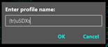
When you start the application for the first time or after a full application reset, you will be prompted to define a new application profile.
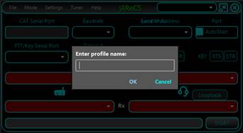
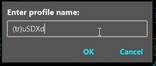
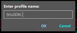
Enter a friendly name for the profile you want to create, like for example ft450ctl (direct control a FT450 transceiver), ft450cli (Control FT450 in client mode), or ft450srv (Control FT450 in server mode) and then press OK.
NOTE: You cannot start the application without defining minimum one valid profile.
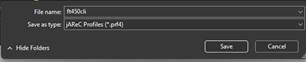
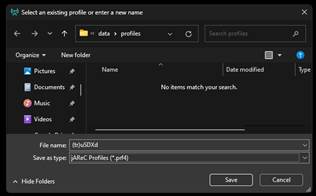
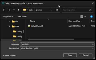
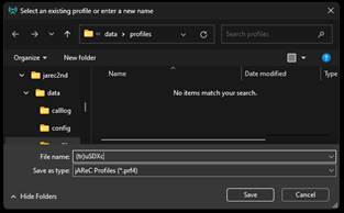
After giving a friendly name, you need to supply a filename for the new profile to be saved into, like ft450ctl in the example below enter the filename and press Save.
Main Menu
Some of the menu items may not be available in all operation modes.
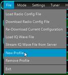
File Menu
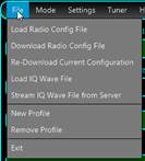
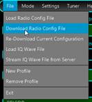
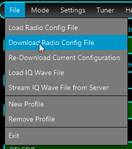
Load Radio Config File – Load a radio configuration file that is available locally.
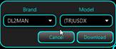
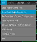
Download Radio Config File – Download a radio configuration file from the central repository. You will be prompted to select radio brand and radio model from the dropdown lists.

When ready, click on the Download button. You will receive a confirmation if the file is successfully downloaded.
Re-Download Current Configuration – Download again the latest available version for the current radio configuration file. You will be prompted to confirm that you want to override existing local config file.
Load IQ Wave File – You will be prompted to select the local IQ wave file you want to load in the application.
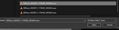
For the supported filename format check here. This must be a standard stereo wave file, left for I and right for Q signals.
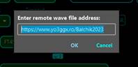
Stream IQ Wave File from Server – You can play an IQ wave file directly from a web server. You must enter the URL of the web page where the IQ Wave files are listed.
![]()
![]()
![]() By default,
an URL hosted on the developer web site is displayed. Can be used to play some
demo IQ Wave files recorded during a context in March 2023. You can enter any
URL you want, but the web page must have the format described here. Click OK to access the web page hosting
the files. A new window will be open, where you can select one of the available
files by clicking on it.
By default,
an URL hosted on the developer web site is displayed. Can be used to play some
demo IQ Wave files recorded during a context in March 2023. You can enter any
URL you want, but the web page must have the format described here. Click OK to access the web page hosting
the files. A new window will be open, where you can select one of the available
files by clicking on it.
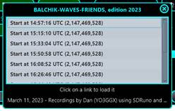
The file will not be downloaded but used to stream the content directly when you start the radio. To learn how to operate with Wave files, click here.
NOTE: When you load a local IQ Wave file or select a remote one, jAReC will automatically load a default radio configuration file named “iq_file.radio4”. Check here to learn more about the format for the radio configuration files.
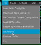
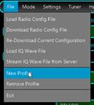
New Profile – create a new application profile. The process is the same as described above under “First Application Start” (see here).
Remove Profile – remove currently selected application profile. If there is only one profile available, this cannot be removed.
Exit – Exit application. You will be asked for confirmation.

Mode Menu
This is used to set the application mode. i.e. what jAReC will do.

The format of the form displayed depends on the last selected operation mode (Server, Client, or Direct Control).
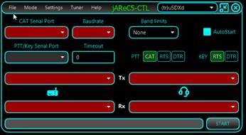
Direct Control
![]()
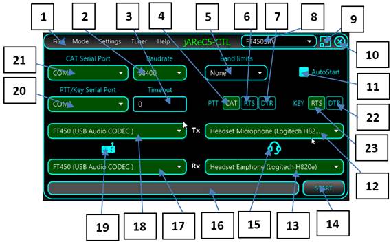
This is the screen displayed when Direct Control has been selected as operational mode.
1 – Application main menu bar.
2 – Baud rate for the CAT serial port.
3 – Timeout in seconds for the PTT. This is used to prevent the situation when the transceiver could remain in Tx mode after a connection lost.
4 – select this button so that PTT is sent via a CAT command.
5 – select ITU region for band limits.
6 – select this button so that PTT is sent using the RTS signal line (see 18 for serial port to be used for PTT).
7 – select this button so that PTT is sent using the DTR signal line (see 18 for serial port to be used for PTT).
8 – Name of currently selected configuration profile.
9 – Button used to minimize the form.
10 – Button used to exit the application.
11 – If checked, when the application is run it will start in the last selected mode of operation and not display this screen.
12 – Indicates the audio device to be used as input (headset) microphone.
13 – Indicates the audio device to be used as output (headset) earphone.
14 – Click this button once all relevant fields are entered to start the selected mode of operation. Check that no selection is red (meaning not selected or currently unavailable). Same for the radio icon if radio audio in or out devices are not selected or not available.
15 – The headset icon will blink if the headset audio in or out devices are not available or not yet selected.
16 – Status bar, used to display different program messages during normal operation.
17 – Radio audio input device (used in Rx).
18 – Radio audio output device (used in Tx).
19 – The radio icon will blink if the radio audio in or out devices are not available or not yet selected.
20 – Serial port to be used for PTT (used only if PTT not sent over CAT, otherwise is disabled).
21 – Serial port to be used for CAT communications.
Once all relevant fields are set, click on the START button to enter Direct Control mode. See here how to operate in this mode. If you check AutoStart, the application will automatically enter Direct Control mode when next started.
22 – When active, radio keying is performed through the DTR pin of the selected serial port.
23 – When active, radio keying is performed through the RTS pin of the selected serial port.
Server mode
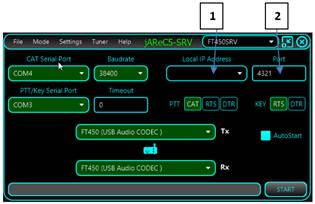
This is the screen displayed when Server mode has been selected as operational mode.
This is the program’s native mode, when connecting from a jAReC v5 client or PocketRxTx5 (when available). The elements displayed in this interface that are the same as in the Direct Control mode have the same usage. These are the new elements:
1 – List of IP addresses available on the local system. This is just for information purposes (to know where to connect to from the client). The server will listen in any case on all available IP addresses of the PC. You don’t have to set this combo box to a specific value.
2 – The TCP port used to connect from the client this needs to coincide with the TCP port number defined in the client program. The same port number will be used for the transfer of waterfall, audio spectrum and audio data between the server and the client programs.
After you press START the same radio control window will appear as in Direct Control mode. Some of the functions can still be used directly from the Server but mirrored on the client too.
NOTE: You cannot start connection to the radio from the Server, only from the Client.
When in Server mode listening for client connection, you will be able to initiate the transfer of configuration files to and from Pocket RxTx5 (when available). Nothing extra to be configured on the server side. Only *.radio4, *.jpg files associated with the radios are transferred.
NOTE: jAReC5 contain all the radio config files and pictures available at the date of the compilation. If central repository is not available, you can use the embedded files. With each application update, configuration files are updated too.
Client mode
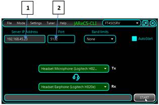
This is the screen displayed when Client mode has been selected as
operational mode.
1 – Enter the IP address or the fully qualified domain name for the jAReC server that you want to connect to.
NOTE: If testing by running a second copy of jAReC as the client on the same PC that is running jAReC in server mode – the “localhost” IP address of 127.0.0.1 can be entered here).
2 – Enter the TCP port (this must match the port number set in the server program).
This mode is used to remotely connect to a previously installed jAReC server instance.
The remaining fields have the same usage as in the Direct Control mode.
Cfg Builder
The last option at the bottom of the Mode pull-down menu will launch the configuration builder utility. This is a graphical tool to help users create, edit and test radio configuration files to avoid the requirement of editing the file manually, so reducing the chances of corrupting a radio file. For more details about the configuration builder, check the dedicated chapter here.
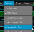
Settings Menu
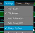
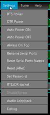
This is how the settings menu looks in Direct Control mode. Some menu items are disabled in different modes.
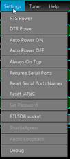
RTS Power, DTR Power – When checked, RTS and/or DTR signals in the CAT serial port are set high (1). This can be useful for some CAT interfaces that are powered from the serial port. Please be aware that these settings does not apply to the second serial port (PTT/Key).
Auto Power ON, Auto Power OFF – When checked, the radio is automatically powered on and/or off when jAReC connects/disconnects from the radio. For this feature to work, a CAT command SET_POWER must be defined for the radio being used.
Auto Info – When SET_AUTOINFO command is defined in the configuration file, this menu item become active. When selected, the radio is auto configured to send parameter values when changed, without requiring a READ command sent by the application.
Always On Top – When activated, the radio control window remains on top of other windows.
Rename Serial Ports – You can give friendly names (aliases) for the serial ports. To rename a serial port (CAT or PTT), click on this menu item. The serial ports background will change from Green to dark gray and you can edit the name.
Enter the desired name (minimum 4 letters) and then press ENTER. The new alias for the port will be visible with a green background.
NOTE: You can rename only one port at a time. To rename another port, click again on Rename Serial Ports and follow the same procedure.
Reset Serial Ports Names – Click on this menu item to return to the standard serial port naming.
Reset jAReC – This will remove the jAReC configuration file and all existing profile files. jAReC will restart with factory default settings.
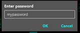
Set Password – This is used in Client and Server modes to set the connection password.
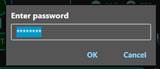
If the password was previously saved, it will be displayed as asterisks. When you enter a new password, is visible in clear text.
NOTE: The password is case sensitive, so take care to enter the same password for both Client and Server ends (including Pocket RxTx5).
RTLSDR socket – this is used when connecting to a local or remote rtl_tcp server. For more details, check the dedicated chapter here.
ShuttleXpress – This menu item will be visible only in Direct Control and in Client modes and only if a ShuttleXpress device was connected to the PC before starting the application. Click on it to start ShuttleXpress configuration. A new form will be opened.
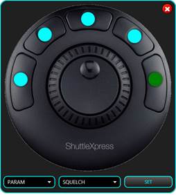
Click on the round dot assigned to the button you wish to configure, or directly on the corresponding button from the ShuttleXpress. The selected button dot will become green. You will be able to select any available parameter for the radio, or one of the following commands: CONNECT, MUTE, PTT, PTTLCK or TUNE. Only five buttons are user configurable. By default, the buttons are programmed as follows: 1 – PTT, 2 – PTTLCK, 3 – CONNECT, 4 – TUNE, 5 – SQUELCH. Click SET when you have changed the buttons that you wished to change.
The central knob is used for fine tuning, or to adjust a parameter. If a button is assigned a parameter, click on the button to set the parameter, use the knob to adjust its value and then click again to return to the default function of the knob (frequency tuning). The crown is used for fast frequency tuning only (UP/DOWN). The tuning step is increased with the rotation angle (left for frequency down, right for frequency up).
Audio Loopback – This can be activated when in Server mode to help troubleshoot audio issues between server and client. No matter what audio in and out interfaces are selected for the radio, any audio from the client is automatically returned by the server. This can be used in Rx mode too.
Debug – When activated, a debug text file (jarec.log) will be created in the application root folder. The log file use timestamps for any logged event.
Example:
14:49:49 : start action
14:49:51 : main form closed
18:07:09 : start action
18:07:10 : cat port unavailable
18:07:10 : main form closed
When in Debug mode, raw meter value is displayed in the lower left part of the meter (for the currently selected meter).
This can help you set meter calibration values in the radio configuration file.
NOTE: Debug mode is automatically disabled when you restart the application.
Tuner Menu
This is used to select what’s happen when you click on the TUNE button.

None – no tuner available, so TUNE button will do nothing
Transceiver – Internal transceiver ATU is used (or an external unit directly controlled by the radio). Clicking on the tune button will start the automatic antenna tuning process.
External – A manual external tuner is being used. Pressing on tune, the transceiver will be set to a predefined mode and power (usually FM/1W) and PTT will be activated. Click here to see how you can configure the mode and power to be used for tuning.
NOTE: Take care that if you use CW, is possible that the radio is not keyed correctly during tuning or SWR scanning.
BTMLC – This will be used for a (B)lue(T)ooth (M)agnetic (L)oop (C)ontroller that is under development. More details will be available later.
Help Menu
From here you can access this application user guide, some info about the current environment and links to different kind of information related to jAReC or other of my hardware and software projects.

Content – provides access to the multilingual online application user guide (in fact exactly the same as this document, but in HTML format)
History – Will display the application history starting with the first v4 beta release.
Donate – Pressing this causes a direct PayPal link to appear. If you want to contribute to the further development and support of this application, please do so.
About – Displays some information about the OS, java and application version in use, OS architecture, compilation date as well as a link to the developer web page.
jAReC Forum – Clicking this will access the jAReC v4 section of YO3GGX’s Forum. Please use this forum for any questions related to this application and to report issues or bugs.
My Applications – Gives access to the web page with all my published applications.
My HW Projects – Gives access to the web page with documentation for all my published hardware projects.
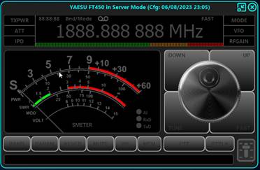
Direct Control mode
After you configure the mode as described here, press the START button. The main radio control window will open.
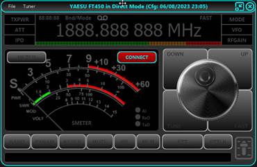
Click on the CONNECT button to connect to the radio. If the connection is successful, all the parameters defined in the radio models “radio” file will be read from the radio and the display adjusted accordingly.
The example below is for a Yaesu FT450D.
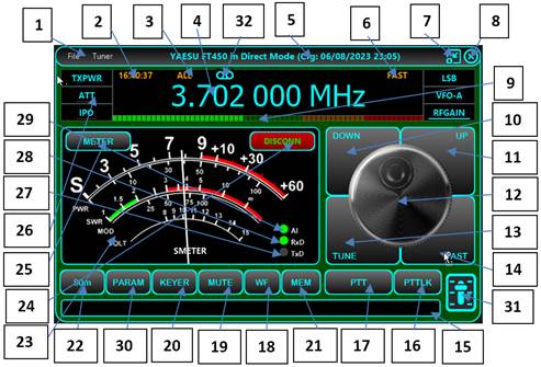
Controls - description:
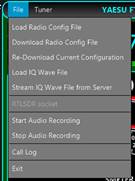
1 – Radio window bar menu. From the File dropdown menu, you can load, download, or re-download a radio configuration file, load an IQ Wave file, select a remote IQ wave file stream, set the socket for RTLSDR operation, start/stop audio recording, open call logging, or exit this radio panel.
To learn how to operate the Call Logging feature, click here.
The Tuner dropdown menu has the same functionality as the one described here.
2 – UTC clock. This is continuously updated when the radio is connected.
3 – For the current frequency, the band and preferred operation mode is displayed here.
4 – The frequency display. The frequency may be displayed in kHz, MHz or GHz. By clicking on the frequency display, the following form will pop-up:
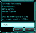
You may enter the desired frequency in MHz. You can optionally add the mode name on the end. For the mode name you can use just the first letter (l=lsb, u=usb, a=am, f=fm, c = cw). If special modes are defined in the radio config, add the full mode name (ex. user-l).
5 – Here is where the radio brand, model and current app operation mode is displayed, including the timestamp of the radio configuration file.
6 – FAST is displayed in orange when FAST tuning mode is activated.
7 – Application window minimize button.
8 – Application window exit button.
9 – A level meter for the Rx or Tx audio.
10 – Step frequency down. Steps are defined in the configuration file, see here.
11 – Step frequency up. Steps are defined in configuration file, see here.
12 – Tuning knob. This can be operated by using the scroll wheel on the mouse or rotating the knob with the mouse or touch gesture (for devices with a touch screen). Tuning step is always 10Hz, or 100Hz if you keep Left Ctrl key pressed when tuning. When FAST mode enabled, tuning step for the knob is 10 times higher (100Hz/1KHz).
13 – TUNE button. See here how this button operates based on the selected antenna tuner mode.
14 – FAST button. When activated, “FAST” is displayed (orange) in the top right corner of the frequency display and tuning step is increased 10 times (for the tuning Knob) or “Brute step” used for the UP/DOWN buttons.
15 – Status message bar, used to display error or informative messages.
16 – PTTLCK button. This is used to lock PTT to ON (ex. For handsfree operation). Shortly click on PTT to set PTT to off.
17 – PTT button. Used to set the transceiver in Tx only when the button is pressed.
18 – Button used to display the Waterfall (and/or spectrum) and audio spectrum. Click here for more details about how to use the waterfall/spectrum.
19 – MUTE button. This will toggle mute of the audio from the radio (if audio routing is being used).
20 – KEYER. Enter the Keyer panel. This feature allows you to send pre-typed CW. More details about this feature can be found here.
21 – MEMORY. Save current frequency, mode and other settings into, or recall from, one of the 16 available memories. More about working with memories here.
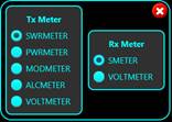
22 – BAND selection button. Pressing this brings up a selection panel to switch to bands supported by this radio.
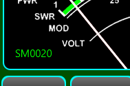
23 – Analog meter used to display one of the following values (see point 20 below): S, SWR, PWR, ALC, MOD, VOLT – if they are supported by this radio’s CAT command set.
24 – Button used to connect or disconnect from the radio via a serial, USB or Bluetooth port.
25 – Use this button to select what meter should display during Rx and Tx. Selection is done in the pop-up window shown below. If a specific meter is not defined in the radio configuration file, you will not be able to select it.
26 – 6 parameters are directly accessible from the main radio window. These are the first 6 parameters from the LSTPARAMS list defined in the radio configuration file. When the radio is connected, the parameter name is displayed in cyan color.
· If the parameter has 2 values, OFF and ON, it will be show as below.
|
|
OFF |
|
|
ON |
· If the parameter can have multiple discrete values, current value will be displayed.
![]()
· If the parameter is covering an interval (linear value), a level bar is displayed, proportional with the current value (between min ad max values).
![]()
You can hover the mouse over the parameter’s box to get more details and possible values for that parameter.
Click on the parameter to change the current value. There are 3 possible situations:
· Parameter with only two values (ON/OFF). The parameter value will be toggled, and the new value displayed accordingly (see text under point 21 above)
· Parameter with multiple discrete values (e.g. for MODE) – a selection panel will be displayed.
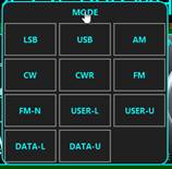
Click on the value you want to set. The parameter is set, and the form is automatically closed.
· Parameter with linear scale values. The following form is displayed:
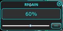
Use your mouse to adjust the slider to the desired value. Click on the MID button to set the parameter to the median value. This can be very useful if you have values that go from negative to positive (symmetrically). In that case you will easily set the parameter to 0.
NOTE: You can adjust the parameter even without clicking on the label, by just hovering over the label and using mouse scroll wheel.
27 – TxD virtual LED. This LED will flash when CAT data is sent to the radio
28 – RxD virtual LED. This LED will flash when CAT data is received from the radio
29 – AI (Auto Info) virtual LED. This LED will be ON when Auto Info is activated (the radio automatically sends parameters value when changed, without a READ command sent by the application.
30 – Parameters selection button. Click on this button to display a panel with all the available parameters to be set for the current radio.

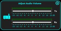
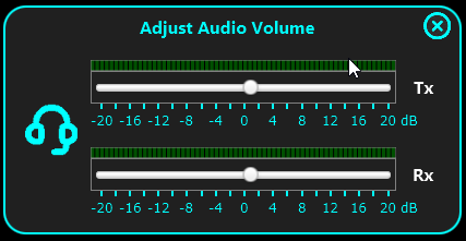
31 – Audio volume adjustment panel. The panel will contain only the volume sliders available for the current mode of operation.
|
Direct control |
Client |
Server |
|
|
|
|
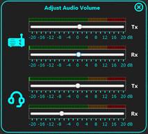
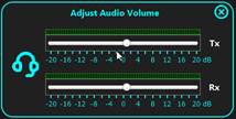
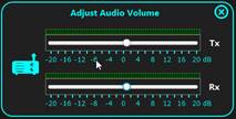
You can independently adjust the volume level for each audio in or out channel. Live audio level is shown on the LED-meter associated with the respective slider.
NOTE: This is not system audio volume, but the application own volume For best results (highest dynamic range) in client-server mode, try to keep the volume for the radio (Rx) and headset (Tx) as close as possible to the yellow region of the LED-meter
32 – Audio recording icon. If audio recording is started, this icon goes red and start flashing.
ATTENTION for Yaesu FT817/818 users !!!
Some of the parameters can be controlled only by a direct write in the radio EEPROM. This is a dangerous operation! If used incorrectly, you may erase radio calibration data, that will require a recalibration in an authorized Yaesu service center. This application takes several precautions to prevent this:
· Forbid sending dangerous CAT commands even if you wrongly edit the radio configuration file
· Does not allow you to write commands that intend to write forbidden parts of the EEPROM (where calibration data is stored).
· When you connect to an FT817/FT818 for the first time, all the factory calibration data is saved in a local text file (checked 2 times, to be sure the values are correctly read).
Working with memories
Click on MEMORY button in the radio panel to open the memories panel.
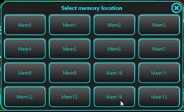
You can load up to 16 memory locations. In each memory location, all defined parameters are saved.
A long press on a memory button until the background goes green will store the current settings. You will then be prompted to enter a label for the memory location.

Click the Save button to save the settings to that memory location.
When you click again on the MEMORY button on the radio panel you will see the previously saved memory(s).
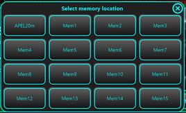
Click on a defined memory location to recall all saved settings into the radio.
Call Logging
When in Direct Control mode or in Client mode, by clicking on the File > Call Log menu item or simply pressing the “L” key on the keyboard you will enter the Call Logging applet. A new form will be displayed that is attached to the radio control form’s right-hand side.
NOTE: The current jAReC version only supports ADIF (version 3.1.1.) as the call log file format.
NOTE: To use all the available download features, you must have a paid QRZ.com XML subscription. With a free QRZ.com account, you will be able to get only some basic info about a registered callsign (Name, QTH and Country).
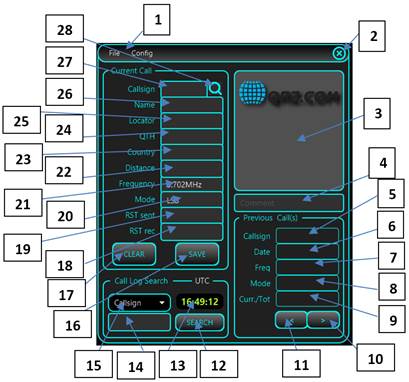
1 – Call Log Window menu bar, containing File and Config menu sections.
The File pull down Menu is used to create a new Call Log file (New), to open an existing Call Log file (Open) or to save currently loaded Call Log under a different filename. When you start Call Log for the first time, you are prompted to create a new Call Log file or load an existing one (for search or edit/append purposes). The call log files are stored in the config folder under the folder where you installed jAReC.
Currently the application does not allow you to delete an existing Call Log record, so if you need this, you must edit the log file directly.

The Config menu is used to set your callsign and to enter your QRZ.com credentials. The credentials are only stored locally on your device, encrypted in the jAReC profile file.

Click on QRZ credentials.
You will be prompted to enter credentials and your own Callsign.
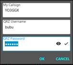
Click OK when ready. If the information you entered is valid, a message will be displayed in the main radio panel status bar, stating that your subscription is validated, when the subscription expires (or “non-subscriber” if you are using a free qrz.com account) and the number of queries you have performed.
![]()
Any QRZ query is performed using a session key, obtained based on your username and password when you start the application and enter Call Logging. If you leave the Call Log window open for a longer period (hours or days), the session key may expire. If at some point you no longer get data for a callsign that is defined at qrz.com, try to resolve this by clicking on Config > (Re)Get QRZ Key. A new key will be generated.
If your qrz.com credentials username or password is invalid, you will get an error message in the main radio panel status bar.
![]()
2 – Exit button. Is used to close Call Logging feature panel (this can also be done by selecting file/exit).
3 – When querying the QRZ database, and you have an XML subscription, the picture used on qrz.com for this station will be displayed here, if any is available.
4 – You can enter a comment for each call log record. This is optional.
Previous Call(s) section is used to display the results when you do a log search in your currently loaded file (see Call Log Search section below).
5, 6, 7, 8 – Previous log entry showing Callsign, Date, Frequency and Mode for the entered call sign in the search box.
9 – Number of search results / number of total calls in the search result list from the log file.
10, 11 – Used to go up/down in the call sign search result list.
12 – Click here to start the search in the currently loaded call log file. You must first select the parameter you want to search for (15) and then enter the text to search for (14).
13 – Here is displayed the UTC clock, that will be used for entering any new contact log record.
14 – Here you enter the text you are searching for in the currently loaded log file. This can be a substring of the field value.
15 – Select from the dropdown list in which field of the call record you want to search, matching against the text in (14). You can choose between: Callsign, Country, Band, Continent, CQ zone, DXCC, ITU zone, and IOTA reference.
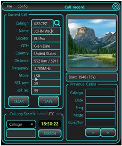
Current Call section. Here is where you enter the data for a new contact. If you have a valid paid QRZ.com XML subscription, you only need to enter the callsign of your correspondent and then press ENTER or click on the search button (28). All the other fields will be automatically filled in, except RST sent (19) and RST rec (18). (If using a free qrz.com account, the Name, QTH and Country fields will be completed).
16 – SAVE button. In order to save a call record in the log, the following fields are mandatory: Callsign (27), Frequency(21), Mode (20), RST sent (19) and RST rec(eived) (18). Frequency and Mode are automatically filled in for you from the radio panel. If the QRZ query is successful (callsign registered in QRZ.com), you only must fill RST sent (19) and RST rec(eived) (18) fields and then to press SAVE button. Call start and end time and date are automatically set based on the current UTC values at the time of log entry.
17 – CLEAR button. If you don’t want to save the current contact to the log, click on CLEAR to clear all of the call information from the form. All fields will be cleared out except Frequency and Mode, that are automatically updated from the radio panel.
18, 19 – RST rec (the RST you received from the other ham) and RST sent (the one you gave to the other ham for the current contact).
20 – MODE field for the current call. This is automatically filled from the radio panel but can be overwritten.
21 – FREQUENCY field for the current call (in MHz). This is automatically filled from the radio panel but can be overwritten.
22 – The distance between your station (if you have a valid record in QRZ.com and an XML subscription account) and the station of your contact. This is automatically calculated based on Locator (25) field, cannot be overwritten by the user and is displayed in both miles and kilometers. This is how it looks (no real data used in this example).
23 – Contacts’ Country – automatically returned from a QRZ query, but you can edit this field
24 – Contacts’ City or County (QTH) – automatically returned from a QRZ query, but you can edit this field.
25 – Contact’s Maidenhead Grid Square Locator – automatically returned from a QRZ query (only with an XML qrz.com (paid) account), but you can edit this field.
26 – Contact’s operator name – automatically returned from a QRZ query (only with an XML qrz.com (paid) account), but you can edit this field.
27 – Contacts’ call sign. You must enter this field manually, for each call. Press enter after entering this to initiate the qrz.com lookup.
28 – Click on this button (or press ENTER) after you enter the callsign to start querying the QRZ database.
If you have a paid QRZ XML subscription, you can click on the station picture to get more information about the station. A new form will be opened. The fields are the standard ones from a call log entry. MQSL (Manager QSL), EQSL, or LOTW labels are displayed with green background if that specific method to receive QSLs is accepted, red if not.
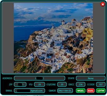
If you click on the picture from this panel, the station’s web page will be displayed (if defined in the QRZ database). If not, the standard QRZ web page for the station will be displayed.
You can search through the current log for specific records (see 12, 14 and 15). Let’s try for example, to search for all contacts with Germany. Select Country as field and enter Germany as search text, then click on SEARCH button.
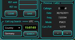
In the example above, there are 219 logged contacts with stations from Germany. Callsign, date, frequency and mode are directly displayed. Use “<” and “>” buttons to browse through the results list. Click on the callsign (from Previous Call(s) section) to query QRZ database about that callsign.
KEYER
Click on the KEYER button when in the radio panel to enter the CW keyer. The following panel will be displayed.
As soon as you enter the Keyer, the radio will be automatically set to CW mode.
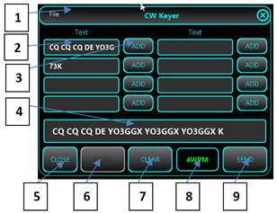
1 – Keyer window menu bar. Use File > Save to save current macros definition after you enter or edit them.
2 – pre-set text sequences. You can define up to 8 text macros to be used with a simple click.
3 –ADD button to add the chosen macro text to the box containing the text to be transmitted (4).
4 – Box containing the text to be transmitted. You can enter/edit the text using the keyboard and/or add predefined text from one of the 8 locations (2).
5 – Button used to close the Keyer panel.
6 –STOP button to immediately stop an in-progress transmission.
7 –CLEAR button to clear the contents of the transmitted text box (4).
8 –Transmission speed (in words per minute). This setting corresponds to the setting in the radio’s configuration file and is user adjustable. Use mouse scroll wheel to adjust it when the mouse pointer is over the black WWPM label.
9 –SEND button to send the text from (4) in CW. PTT and CW KEY interface settings are explained here.
When you click on the CLOSE (white X on red background) button the Keyer panel is closed, and the radio is set back to the mode it was in before the keyer panel was activated.
Server mode
In this mode, your computer will act as a server for the transceiver, allowing another instance of jAReC in Client mode (or the PocketRxTx v4 Android application, which is not yet available) to connect over the network (LAN or Internet) and control the radio. To configure this mode, check here. When ready, click on START. You can set jAReC to automatically start this mode when application run by setting AutoStart.
Standard radio panel will be displayed, but without any usual configuration options.
jAReC server, in this picture, is waiting for a connection from a jAReC5 (or PocketRxTx5) client. The radio panel of the server and the client program will be kept continuously in sync. As soon as the connection is successfully established, the server panel will have the same appearance as in Direct Control Mode, but without local control. The background will go dark green when the client is connected dark red when radio is in Tx mode.
Client mode
This mode is used to connect to your radio over the network, through another jAReC instance in server mode. For details about how to configure this mode, check here. When clicking on the START button, the same radio panel as in Direct Control mode will be opened. You then can operate the Client mode in the same way as Direct Control mode, as described here.
NOTE: Most of the items from the Settings menu (describe here) must be pre-configured in the server panel, are unavailable on the client.
Using Audio spectrum, audio DSP and app Squelch
These features are available for all radios and is implemented directly in jAReC5. This allows you to display the spectrum of the received audio signal, configure the filters (low pass, band pass and/or band reject directly from the GUI, adjust Squelch level, and display decoded CW data (not yet implemented).
To open audio spectrum window, click on WF button.
NOTE: When a radio with Waterfall support is selected, both Waterfall and Audio Spectrum windows are open when you click on WF button.
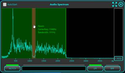
Audio Spectrum Window in Rx mode
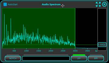
The window looks like in the following picture. By default, the window is started with the LPF (low pass filter) activated.
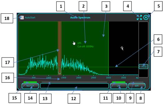
1 – Form label. Click on it and drag it to move the windows around the screen. Last position is saved in the configuration file.
2 – A label showing the setting for the currently selected filter. When outside a filter area, shows the audio frequency in that point.
3 – Filtered area is shown in a color. Green is used for low pass (LPF) and band pass (BPF) filters, red for notch filter. BPF and LPF cannot be selected in the same time, but one of them is always selected.
4 – Click on this icon to set this window full screen. When in full screen mode, icon change and is used to restore previous dimensions.
5 – Click on this icon to close Audio Spectrum window.
6 – A line showing current Squelch level. When Squelch is open, line is green, when closed (or radio muted), is red.
7 – Squelch level adjustment button. Slide the button vertically to adjust it. The green/red line is moved too.
8 – Click on this button to activate the band pass filter (BPF). Click here to learn how to adjust the BPF.
9 – A virtual LED showing when BPF is activated.
10 – Click on this button to activate the low pass filter (LPF). Click here to learn how to adjust the LPF.
11 – A virtual LED showing when LPF is activated.
12 – Then in CW mode, CW decoded data will be shown in this area (not yet implemented).
13 – This virtual LED will light when dit or dah are received in CW mode.
14 – Click on this button to activate the NOTCH filter. Click here to learn how to adjust the NOTCH filter.
15 – A virtual LED showing when NOTCH filter is activated.
16 – Audio frequency scale.
17 – NOTCH filter area (displayed in red).
18 – Check this box to automatically open Audio Spectrum window when connected to the radio.
Audio Spectrum Window in Tx mode
The window looks like in the following picture. By default, the window is started with the BPF (low pass filter) permanently activated.
ASQL button change to COMP and now is used to adjust audio compression level for Tx. 0 is at the bottom, maximum at the highest position. The rest of the controls looks similar.
Adjusting Low Pass Filter (LPF)
First check that the LPF is activated. To adjust the cut-off frequency for the LPF, you have two options:
· Keep mouse cursor over the filter green area and use mouse scroll wheel to increase/decrease cut-off frequency. The display is adjusted automatically, and you can see the effect on the audio spectrum.
· Click and drag mouse cursor horizontally in the green area.
In both cases, the filter is updated as soon as you release the mouse button or scroll wheel. You will hear a short audio dropout, showing that new filter parameter was applied.
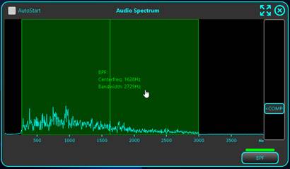
Adjusting Band Pass Filter (BPF)
First check that the BPF is activated.
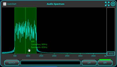
Keep the mouse cursor over the filter green area to see current settings (center frequency and bandwidth). To adjust center frequency, drag with the mouse the green area to the left or right. The label with the parameters will be automatically updated, but the filter will be applied only when you release the mouse.
To adjust the bandwidth, keep the mouse cursor over the green area and use the scroll wheel to increase/decrease the bandwidth. The filter will be applied shortly after you release the mouse wheel. You will hear a short audio dropout, showing that new filter parameters were applied.
NOTE: BPF and LPF cannot be used in the same time.
Adjusting NOTCH Filter
First check that the NOTCH filter is activated. NOTCH filter is used at the same time with the BPF or LPF filter. Can be very useful to remove unwanted signals overlapped over the received signal. Minimum bandwidth is 10Hz. This is just to allow you to still select it with the mouse.
Keep mouse cursor over the filter red area to check current parameters (center frequency and bandwidth). Drag the red area left or right to adjust center frequency. Parameters label is automatically adjusted. Keep the mouse cursor over the filter red area and use scroll wheel to adjust NOTCH filter bandwidth. The new parameters are applied shortly after you release the mouse button or scroll wheel. You will hear a short audio dropout, showing that new filter parameters were applied.
Using the Waterfall
Waterfall is available only for radios involving internal jAReC5 SDR engine, or selected radios that provides waterfall data over the CAT connection (currently only some Icom radios: IC7300, IC705, IC9700, ICR8500, IC7850 and IC7610.
NOTE: When this document was edited, radio configuration files are available only for IC7300 and IC705. The rest will follow.
Waterfall is available only in Direct Control or Client modes and has always an horizontal resolution of 1024 samples (when in internal SDR mode) or only 475 samples (with iCOM radios, limited by the available CI-V CAT protocol). The horizontal resolution does not change when going full screen, so the image clarity can decrease.
Waterfall with internal jAReC5 SDR engine
In the current version, internal SDR engine is used for the following radios:
· RTLSDR dongles over rtl_tcp. Check this chapter to learn how to use a RTLSDR dongle.
· RSP1A dongles over rsp_tcp. Check this chapter to learn how to use a SDR Play RSP-1A receiver.
· IQ based receivers (ex. Softrock, Malahit DSP) or transceivers with IQ output. Check this chapter to learn how to use an IQ based receiver (or transceiver in Rx).
· Local IQ wave files. Check this chapter to learn how to play local IQ wave files.
· Remote IQ Wave files. Check this chapter to learn how to play remote IQ wave files.
When you use one of the above radios, click on WF button to open the Waterfall.
NOTE: Audio Spectrum window will be open at the same time with the Waterfall one. Check here to learn how to use Audio Spectrum window.
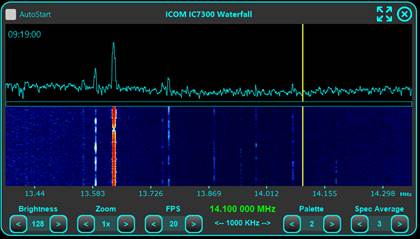
This is how the waterfall window looks.
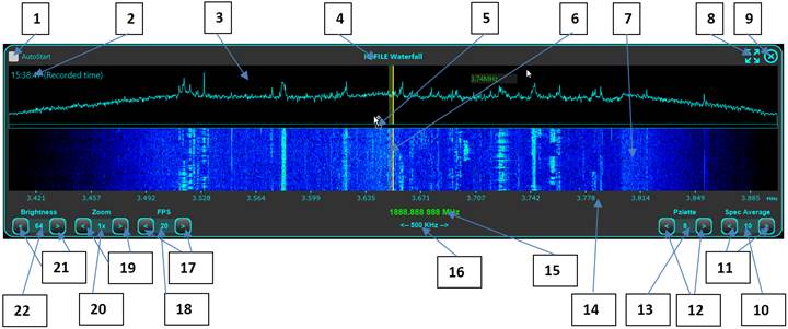
1 – Check this box to automatically start the waterfall when connecting to the radio or file.
2 – UTC clock. When in file mode, this is the UTC time at the moment recording was made.
3 – Spectrum area.
4 – Drag the window label with the mouse to move it around the screen. Last position is automatically saved.
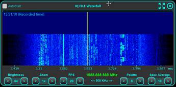
5 – Drag vertically this separation line with the mouse to set split ratio between the spectrum and waterfall areas. When full up, only the waterfall is displayed. When full down, only the spectrum is displayed.
|
|
Full up, only waterfall displayed. |
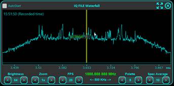
|
|
Full down, only spectrum displayed. |
6 – Frequency reticule. When in LSB, USB, AM or FM, the yellow vertical line shows the tuned frequency. The semi-transparent yellow area represents the audio bandwidth. When in CW mode, the tuned frequency is the center of the audio bandwidth.
7 – Waterfall data.
8 – Click on this icon to set this window full screen. When in full screen mode, icon change and is used to restore previous dimensions.
9 – Click on this icon to close Waterfall window.
10 – To smooth the spectrum display, an averaging method is used between consecutive packets. This label shows current averaging number (between 1 and 20).
11 – Up/Down button used to adjust averaging level.
12 – Up/Down button used to select waterfall palette. Currently 8 color palettes are available, select the one you prefer.
13 – Label to display currently selected waterfall color palette.
14 – Frequency scale.
15 – Currently tuned frequency.
16 – Current waterfall/spectrum bandwidth.
17 – Up/Down button to select waterfall framerate in frames per second. Value can be between 1 and 30.
NOTE: This parameter does not apply when connected to a supported iCOM radio, as then the waterfall data is received at much a lower framerate, dependent on the BaudRate and connection mode (serial or network). Currently only serial connection is available.
18 – Label to display current waterfall/spectrum framerate (in frames per second).
19 – Up/Down button to select waterfall zoom.
20 – Label to display currently selected waterfall zoom.
21 – Up/Down button used to adjust waterfall brightness. This in fact adjust the minimum value and does not affect spectrum display. The value can be between 0 and 128, with step 2.
22 – Label to display current brightness level.
Waterfall with supported radios from iCOM
Currently only some iCOM radios are supported: IC7300 and IC705. More will follow as soon as the configuration files will be available. To use the waterfall, please check in the Settings menu that Auto Info is activated.

NOTE: When waterfall window is active, only FREQ, MODE, FILT and SMETER parameters are updated when are changed directly from the radio.
Click WF button to open the waterfall window. The waterfall will look and operate the same as in the internal SDR mode. To learn how to operate it, check this chapter.
The waterfall limitations for the supported iCOM radios are the following:
· FPS cannot be adjusted. Is fixed by the CI-V CAT protocol and depends on the serial BaudRate.
· Horizontal resolution is only 475 pixels, no matter the windows size. This is an iCOM protocol limitation.
· If waterfall is to dark or to bright and Brightness adjustment is not enough use the SCOPEREF radio parameter (see Parameters panel here for more details). You can adjust waterfall level with up to +/- 20dB.

· Waterfall is supported only if the SCOPMODE parameter is set to FIXED. This is done automatically, do not try to change it manually.
![]()
· SCOPESPD (scope speed) parameter does not affect waterfall display in jAReC5, only on the radio.
· WFBW (Waterfall resolution bandwidth) must be kept to the lowest available value (40KHz) for best waterfall resolution.
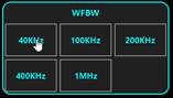
· VBW (Waterfall Video Bandwidth) must be kept to NARROW for best waterfall resolution.
![]()
· Waterfall is supported only if the SCOPDATA parameter is set to ON. This is automatically set when starting the waterfall, do not try to change it manually.
![]()
Tunning the radio using the waterfall
When you hover the mouse over the spectrum/waterfall, the frequency corresponding to that point is displayed.
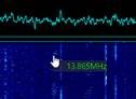
Currently set frequency is displayed by a yellow vertical line, covering both waterfall and spectrum area. Audio bandwidth is represented by a semitransparent yellow vertical strip.
You can easily tune the radio using only the waterfall with one of the following gestures:
· Click anywhere on the waterfall to set radio frequency to that value.
· Drag the mouse cursor over the waterfall or spectrum to continuously change the frequency.
· Use mouse scroll wheel to adjust the frequency. Use LEFT CTRL or LEFT SHIFT key to modify the step. This is a table showing the effect of FAST and CTRL/SHIFT key pressed when tuning using the wheel. SHIFT key has precedence if CTRL key pressed in the same time.
|
FAST |
SHIFT Key pressed |
CTRL Key pressed |
Resulting Step [Hz] |
|
OFF |
NO |
NO |
Fine step |
|
OFF |
NO |
YES |
Brute step |
|
OFF |
YES |
NO |
10Hz |
|
ON |
NO |
NO |
Brute Step |
|
ON |
NO |
YES |
10*Brute step |
|
ON |
YES |
NO |
10Hz |
· When you reach the end or the beginning of the waterfall, central waterfall frequency is automatically adjusted to that value. If previous zoom was > x1, then will be automatically reset to 1x.
Using jAReC5 with a (tr)uSDX radio
To access all the features available in jAReC5 for a (tr)uSDX radio, minimum supported firmware version is 2.00u.
The main feature of (tr)uSDX that require a specific jAReC5 configuration to work is audio over the serial connection. This is available for both Rx and Tx and allows you to bypass internal radio audio channels (mic and speaker), that because of the extremely simplified architecture does not provide a good audio quality. You will be able to operate the radio even from a wireless Bluetooth headset connected to your PC/Mac/Raspberry Pi.
This mode may work with other transceivers from the uSDX family too, with specific versions of the open-source firmware. If you test my application with this kind of transceivers, please send me your feedback.
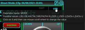
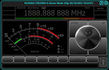
(tr)uSDX radio in Direct Control mode
Connect power to the radio and then your radio to the PC/Mac using an USB to microUSB cable. Follow the below steps.
NOTE: Steps order is important, so please do not change actions order, otherwise some steps may be required to be repeated.
· Define a new application profile. If you start the application for the first time, you will be automatically prompted to create a new profile. If not, you can do it from the startup page File > New Profile menu.
· Enter a profile name (ex. (tr)uSDXd, with ‘d’ suffix for Direct control, to easily differentiate between profiles for different modes). The number of characters for the profile name is not limited, but if it is too long, will be displayed truncated in the profiles list combo box. Click OK.
· You will be prompted for a filename for the profile file (*.prf4). Enter a filename (can be the same as the profile name, ex. (tr)uSDXd). Do not modify the default location for the profile file (.\data\profiles). Click on Save button.
· The new profile name will be automatically selected in the profile combo box.
· Download the (tr)uSDX radio configuration file from the central repository. Click on File > Download Radio Config File.
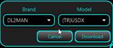
· Select from the list DL2MAN as brand and (TR)USDX as model and click Download.

· Select Mode > Direct control.

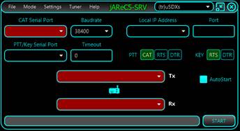
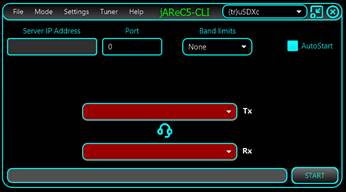
· You will get a form with most of the selections empty and displayed in red. Radio and headset icons will flash, to show you that the audio devices are not available or not selected.
![]()
![]()
· From the Settings menu click to select DTR Power to force DTR to 1. Each time you connect to the radio, the radio will be reset. If you forget this step, CAT control will not be possible. If you want, you can check Always On Top too, to keep the radio window on top all the time.
· Select Tuner None or External (if you have one).

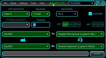
· Select the corresponding parameters from the form:
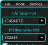
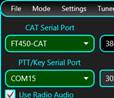
o CAT Serial Port – the virtual COM (USB Serial) port where (tr)uSDX is connected.
o Do not select any PTT Serial port (leave it as it is)
o Set Baudrate to 115200
o Select Radio Tx audio (tr)uSDX (this is not available if you didn’t previously load (tr)uSDX radio config file).
o Select Radio Rx audio (tr)uSDX
o Headset Rx audio – audio playback device used as headset headphone
o Headset Tx audio – audio record device used as headset microphone. As soon as you select all 4 audio devices, radio and headset icons will stop flashing.
o Select PTT over CAT
o Unselect any KEY(ing) selection. This will disable PTT/Key Serial Port combo box.
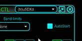
o Set the other parameters (Band limits, AutoStart, PTT Timeout) according to your preferences.
· Click on START button to open main radio window. If you miss one of the steps above, you may not be able to go further and you will get an error message in the status bar.
![]()
· Main radio window will show in the top bar the current radio configuration file and timestamp. Click on CONNECT button to start operating the radio.
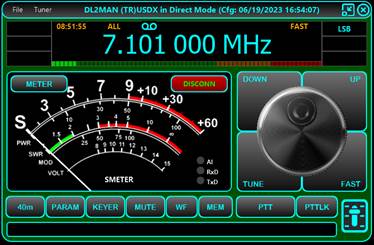
· To learn how to operate the radio interface, check the chapter here.
· You may control audio level for both Rx and Tx using audio volume panel. Click on the slider symbol in the bottom left of the radio window when radio is connected.
· You may use the Audio Spectrum, audio DSP (both Rx and Tx) and audio Squelch/Compander by clicking on the WF button.
· To learn how to operate the internal jAReC5 audio DSP, check the chapter here.
(tr)uSDX radio in Server mode
Connect power to the radio and then your radio to the PC/Mac using an USB to microUSB cable. Follow the below steps.
NOTE: Steps order is important, so please do not change actions order, otherwise some steps may be required to be repeated.
· Define a new application profile. If you start the application for the first time, you will be automatically prompted to create a new profile. If not, you can do it from the startup page File > New Profile menu.
· Enter a profile name (ex. (tr)uSDXs, with ‘s’ suffix for Server mode, to easily differentiate between profiles for different modes). The number of characters for the profile name is not limited, but if it is too long, will be displayed truncated in the profiles list combo box. Click OK.
· You will be prompted for a filename for the profile file (*.prf4). Enter a filename (can be the same as the profile name, ex. (tr)uSDXd).
Do not modify the default location for the profile file (.\data\profiles). Click on Save button.
· The new profile name will be automatically selected in the profile combo box.
![]()
· Download the (tr)uSDX radio configuration file from the central repository. Click on File > Download Radio Config File.
· Select from the list DL2MAN as brand and (TR)USDX as model and click Download.
· Select Mode > Server mode.

· You will get a form with most of the selections empty and displayed in red. Radio icon will flash, to show you that the input and output audio devices for the radio are not available or not selected.
![]()
· From the Settings menu click to select DTR Power to force DTR to 1. Each time you connect to the radio, the radio will be reset. If you forget this step, CAT control will not be possible. If you want, you can check Always On Top too, to keep the radio window on top all the time.
· Select Tuner None or External (if you have one).

· Select the corresponding parameters from the form:
o CAT Serial Port – the virtual COM (USB Serial) port where (tr)uSDX is connected.
o Do not select any PTT Serial port (leave it as it is)
o Set Baudrate to 115200
o Select Radio Tx audio (tr)uSDX (this is not available if you didn’t previously load (tr)uSDX radio config file).
o Select Radio Rx audio (tr)uSDX
o Select PTT over CAT
o Unselect any KEY(ing) selection. This will disable PTT/Key Serial Port combo box.
o Enter the IP address for the server to listen on. Currently the server is listening on all available addresses (0.0.0.0), so use this combo box selection only for information.
o Enter the TCP port to listen on. Starting with jAReC5, only TCP is used, for all communication (including audio). Note this value as it will be used when configuring the client, Set the other parameters (Band limits, AutoStart, PTT Timeout) according to your preferences.
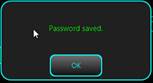
· Click on Settings > Set Password to set the password for the network connection.
· If the password was previously defined, you will see it as ‘*******’. Enter the password (case sensitive) and press OK.
You will see what you type.
· A confirmation message will be displayed. Click OK.
· Click on START button to open main radio window. If you miss one of the steps above, you may not be able to go further and you will get an error message in the status bar.
![]()
· Main radio window will show in the top bar the current radio configuration file and timestamp. As you are in server mode, some buttons are not available (CONNECT and METER), respective function being controlled from the client.
· You are now ready to configure the client as described here and start the radio remotely.
· Radio panel in server mode will mirror the panel on the client. Some controls are still available on the serve too, and this can be helpful for troubleshooting.
· You may control audio level to and from the radio using audio volume panel. Click on the slider symbol in the bottom left of the radio window when radio is connected. This is possible only when connected from the client. Use this to adjust mainly the radio Rx audio interface to have the level for a strongly received audio signal as close to the yellow area of the associated LED meter. This will allow for a maximum dynamic range for the audio transmission over the network.
.
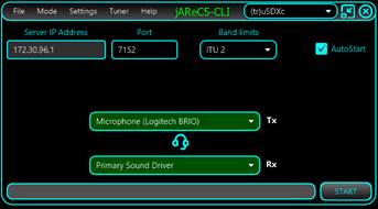
(tr)uSDX radio in Client mode
Using a PC/Mac/Raspberry Pi, run jAReC5 as described here.
NOTE: Steps order is important, so please do not change actions order, otherwise some steps may be required to be repeated.
· Define a new application profile. If you start the application for the first time, you will be automatically prompted to create a new profile. If not, you can do it from the startup page File > New Profile menu.
· Enter a profile name (ex. (tr)uSDXc, with ‘c’ suffix for Client mode, to easily differentiate between profiles for different modes). The number of characters for the profile name is not limited, but if it is too long, will be displayed truncated in the profiles list combo box. Click OK.
· You will be prompted for a filename for the profile file (*.prf4). Enter a filename (can be the same as the profile name, ex. (tr)uSDXc). Do not modify the default location for the profile file (.\data\profiles). Click on Save button.
· The new profile name will be automatically selected in the profile combo box.
![]()
· Download the (tr)uSDX radio configuration file from the central repository.
· Click on File > Download Radio Config File.
· Select from the list DL2MAN as brand and (TR)USDX as model and click Download.
· Select Mode > Client mode.

· You will get a form with some of the selections empty and displayed in red. Radio icon will flash, to show you that the input and output audio devices for the headset are not available or not selected.
![]()
· Select Tuner None or External (if you have one).
· Select the corresponding parameters from the form:
o Select Headset Tx audio (headset microphone).
o Select Headset Rx audio (headset headphones or a speaker).
o Enter the IP address or hostname of the jAReC server you want to connect to (if you are in the same network as the server), or the external IP address (or hostname) of your router where you have to forward the TCP port to the system where jAReC5 server is running. Check router documentation to learn how to configure port forwarding on the router).
o Enter the TCP port to connect to. Is the same as the one configured in jAReC5 server (check here). Starting with jAReC5, only TCP is used, for all communication (including audio) so if you have to forward the port in the router, forward only for TCP packets.
· Click on Settings > Set Password to set the password for the network connection.

· If the password was previously defined, you will see it as ‘*******’. Enter the password (case sensitive) and press OK. You will see what you type.

· A confirmation message will be displayed. Click OK.
· Click on START button to open main radio window. If you miss one of the steps above, you may not be able to go further and you will get an error message in the status bar.
![]()
· Main radio window will show in the top bar the current radio configuration file and timestamp.
Click on CONNECT button to start operating the radio.
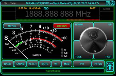
· To learn how to operate the radio interface, check the chapter here.
· You may control audio level for both Rx (headset headphones) and Tx (headset mic) using audio volume panel. Click on the slider symbol in the bottom left of the radio window when radio is connected.
· You may use the Audio Spectrum, audio DSP (both Rx and Tx) and audio Squelch/Compander by clicking on the WF button.

· To learn how to operate the internal jAReC5 audio DSP, check the chapter here.
Current Limitations for (tr)uSDX radio operation through jAReC5
The following limitations applies to jAReC when operating a (tr)uSDX radio (based only on radio firmware limitations as of version 2.00u). This may improve in the future if the (tr)uSDX developers will add new features in the official firmware.
· You can control through CAT only frequency, mode, and PTT.
· No meter available through CAT commands, so the meter will show 0 no matter what meter you select (both Rx and Tx)
· Even (tr)uSDX is a SDR transceiver, IQ data is not user accessible in the current version of the hardware and software (as of July 1st, 2023), so no waterfall available for this radio and you cannot benefit from jAReC internal SDR engine.
· As less than 6 parameters are available through CAT (except Frequency and PTT), PARAM button does not have any effect.
· jAReC KEYER is not functional, as RTS nor DTR cannot be used for this purpose (radio hardware limitation).
·
Using jAReC5 with a RTLSDR/RSP1A dongle
This is a receiver only mode and use the full SDR decoding engine integrated in jAReC5. First you must install and configure the rtl_tcp server on the system where the dongle is connected (for the RSP-1A you must install the compatible rsp_tcp server). The dongle can be connected to the system where jAReC5 runs, or to another computer accessible over the network.
Installing rtl_tcp server on a Windows computer
Do the following (the procedure was tested on Windows 11):
· Download the latest version of Zadig (2.8 as of June 27, 2023) from here: https://zadig.akeo.ie/
· Connect RTLSDR dongle to the PC USB serial port.
· Run Zadig as administrator by right clicking it and choosing run as administrator. No installation is necessary. You can check that the executable is digitally signed, and the signature should state: "Akeo Consulting"
· Go to Options -> List all devices and make sure it is checked
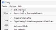
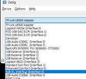
· In the dropdown box choose Bulk-In, Interface (Interface 0). This may also sometimes show up as something prefixed with “RTL28328U”.
That choice is also valid.
· Make sure that WinUSB is selected as the target driver and click on Replace Driver. If WinUSB is already the current driver, the button is named Reinstall Driver.
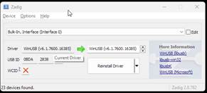
NOTE: If you insert the dongle into a different USB port, you may have to use Zadig again.
· Download the latest 32bit or 64bit rtl_tcp package (depending on your Windows version) from here:
https://ftp.osmocom.org/binaries/windows/rtl-sdr/
· As of June 27, 2023, the latest 64 bit version of the rtl_sdr package is available here:
https://ftp.osmocom.org/binaries/windows/rtl-sdr/rtl-sdr-64bit-20230627.zip
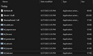
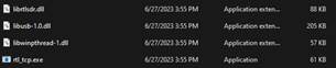
· The following files are included in the package:
· In a command line window, run the test:
>rtl_test
Found 1 device(s):
0: Realtek, RTL2838UHIDIR, SN: 00000001
Using device 0: Generic RTL2832U OEM
Found Rafael Micro R820T tuner
Supported gain values (29): 0.0 0.9 1.4 2.7 3.7 7.7 8.7 12.5 14.4 15.7 16.6 19.7 20.7 22.9 25.4 28.0 29.7 32.8 33.8 36.4 37.2 38.6 40.2 42.1 43.4 43.9 44.5 48.0 49.6
[R82XX] PLL not locked!
Sampling at 2048000 S/s.
Info: This tool will continuously read from the device, and report if
samples get lost. If you observe no further output, everything is fine.
· If you don’t get any errors, then the device is working as expected. Press CTRL+C to stop the test.
· Copy the following files to the jAReC5 addons folder (check here for location). This will allow jAReC5 to automatically start rtl_tcp server if the device is connected to the same PC.
· If jAReC5 is running on another computer, you must manually start rtl_tcp server and to allow inbound TCP connections in Windows firewall for the defined TCP port.
rtl_tcp.exe -a server_ip_to_listen_on -p 1234
· Replace server_ip_to_listen_on with the real server IP. This is mandatory. Without this parameter, the server will listen only for localhost(127.0.0.1) connections.
· If you have multiple RTLSDR dongles, add to the command the device number (first device for rtl_tcp is 0)
rtl_tcp.exe -a server_ip -d devnr -p 1234
· Replace devnr with the RTTLSDR dongle device id (0,1,…). You can have multiple RTLSDR devices connected to the same computer. jAReC5 will be able to connect to all, using separate profiles.
· You can now connect from jAReC5 as described here.
Installing rtl_tcp server on a Linux (Debian flavor) computer
Follow the steps below (applies to a Raspberry Pi OS too):
· Bring the OS up to date (restart require at the end it not already updated)
o sudo apt update && sudo apt full-upgrade -y && reboot
· Install dependencies
o sudo apt-get install -y git cmake libusb-1.0-0-dev
· Clone rtlsdr repository
o git clone git://git.osmocom.org/rtl-sdr.git
· Build rtlsdr
o cd rtl-sdr
o mkdir build
o cd build
o cmake ../ -DINSTALL_UDEV_RULES=ON
o make
o sudo make install
o sudo cp ../rtl-sdr.rules /etc/udev/rules.d/
o sudo ldconfig
· Blacklist the DVB-T Drivers by editing /etc/modprobe.d/blacklist-rtl.conf file (a new file is created if does not exist)
· Add the following lines
o blacklist dvb_usb_rtl28xxu
o blacklist rtl2832
o blacklist rtl2830
· Save the file. Reboot computer.
o sudo reboot
· Login and check note your computer IP address returned by the command
o ifconfig
· Note the IP address of your network interface used to connect to the network (ex. 192.168.25.49)
· Open the firewall for the port to be used for the rtl_tcp server (ex. 1234)
o sudo ufw allow 1234/tcp
· Start rtl_tcp server with the following command (replace IP and port with your values)
o rtl_tcp -a 192.168.25.49 -p 1234 &
o or use:
o rtl_tcp -a 0.0.0.0 -p 1234 &
o to listen on all available IP addresses for the server.
· The server will run in the background. You are now ready to connect from jAReC5 as described here.
NOTE: If you run jAReC5 on the same computer where the RTLSDR dongle is connected, you can use localhost (127.0.0.1) as IP address. Copy the rtl_tcp file
Installing rtl_tcp server on a Mac computer
The procedure to install rtl_tcp on a Mac computer is copied from here.
Consist of:
· Download and extract the archive rtlsdr_osx.zip from https://inst.eecs.berkeley.edu/~ee123/fa12/rtlsdr/rtlsdr_osx.zip
· You should see the files: rtl_sdr, rtl_tcp, rtl_test, librtlsdr.dylib, librtlsdr.0.dylib,librtlsdr.0.0.0.dylib, libusb-1.0.0.dylib
· In the terminal go to the directory path of the archive you downloaded and copy the files to the right place:
sudo cp rtl_sdr rtl_tcp rtl_test /opt/local/bin/
sudo cp lib* /opt/local/lib/
· Connect your USB dongle to your computer and run the rtl_test. You should get something like the following output (Tuner may be differrent):
rtl_test -t
Found 1 device(s):
0: ezcap USB 2.0 DVB-T/DAB/FM dongle
Using device 0: ezcap USB 2.0 DVB-T/DAB/FM dongle
Found Elonics E4000 tuner
Supported gain values (18): -1.0 1.5 4.0 6.5 9.0 11.5 14.0 16.5 19.0 21.5 24.29.0 34.0 42.0 43.0 45.0 47.0 49.0
Benchmarking E4000 PLL...
[E4K] PLL not locked for 51000000 Hz!
[E4K] PLL not locked for 2227000000 Hz!
[E4K] PLL not locked for 1114000000 Hz!
[E4K] PLL not locked for 1241000000 Hz!
E4K range: 52 to 2226 MHz
4K L-band gap: 1114 to 1241 MHz
· If the RSP device is connected to the Mac where jAReC5 runs, copy the file following files from /opt/local/bin/ to the addons folder in jAReC5 ($APP_FOLDER/data/addons).
rtl_tcp
librtlsdr.0.0.0.dylib
librtlsdr.0.dylib
librtlsdr.dylib
libusb-1.0.0.dylib
· This will allow to automatically start rtl_tcp server from jAReC5.
Installing rsp_tcp server on a Windows computer
Follow the guide on the SDRplay to install and configure rsp_tcp server on your Windows computer.
https://www.sdrplay.com/docs/SDRplay_RSP_TCP_Server_Guide.pdf
An extract from that document with the steps to follow is presented below. Please be aware that current version of jAReC5 only supports standard mode for the TCP server (8 bit).
Do the following:
· Go to SDRplay download page here. Select your SDRplay receiver model and Windows version and click Next.
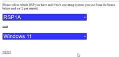
· From Other software section, click on TCP server.
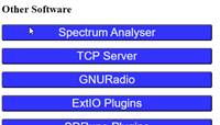
· Select TCP Server (the latest version as of June 28, 2023 is 1.1) and agree with the statement that the software will be used only with genuine SDRplay devices and click on the blue button.
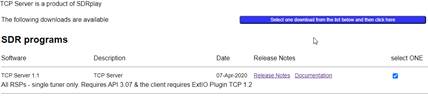
· A zip file (SDRplay_RSP_TCP_1.1_Windows.zip) containing the following files will be downloaded.
![]()
· From the same Downloads page select API/HW Driver 3.11. The file SDRplay_RSP_API-Windows-3.11.exe will be downloaded when clicking on the blue button.

· Double click on SDRplay_RSP_API-Windows-3.11.exe to run it.
· Accept the agreement and click Next.
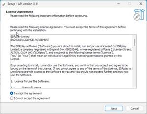
· Confirm that the RSP is not yet connected to your PC and click Next.
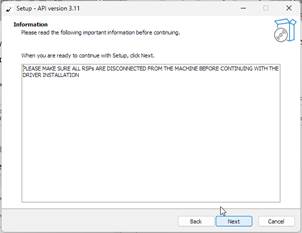
· Keep proposed installation folder and click Next.
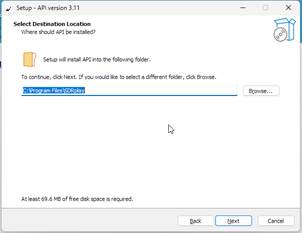
· Click Next, Next, Install. The driver will be installed. At the end, a confirmation window will be displayed. Connect your RSP device to the PC and click Next, then Finish.
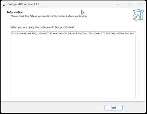
· If the RSP device is connected to the same PC as jAReC5, copy the following files to the jAReC5 addons folder (check here for location). This will allow jAReC5 to automatically start rsp_tcp server.
![]()
· If jAReC5 is running on another computer, you must manually start rsp_tcp server and to allow inbound TCP connections in Windows firewall for the defined TCP port.
rsp_tcp.exe -s server_ip_or_hostname -d devnr -p 1234
· Replace server_ip with the real IP address of the PC where rsp_tcp runs and devnr with the RSP device number. First device is always 1 for RSP. You can have multiple RSP devices connected to the same server. jAReC5 will be able to connect to all, using separate profiles.
· You can now connect from jAReC5 as described here.
Installing rsp_tcp server on a Linux (Debian flavor) computer (RSP-1A only)
This procedure must be used only for RSP-1A receivers. For other SDRplay RSP receivers, check here.
Here an older version of the rsp_tcp server is used, created by ON5HB and available at this location:
https://github.com/ON5HB/rsp_tcp
Do the following for distributions based on Debian (like Ubuntu) and RSP-1A:
· In your home folder run the following commands:
git https://github.com/ON5HB/rsp_tcp.git
cd rsp_tcp
sudo chmod +x SDRplay_RSP_API-Linux-2.13.1.run
./SDRplay_RSP_API-Linux-2.13.1.run
· Read license terms and enter y to install API Version 2.13 then continue:
mkdir build
cd build
cmake ..
make
sudo make install
· You must check not to get any error during the procedure. The rsp_tcp server is now installed.
· If the RSP device is connected to the Mac where jAReC5 runs, copy the file /opt/local/bin/rsp_tcp to the addons folder in jAReC5 ($APP_FOLDER/data/addons).
· Continue here to learn how to configure jAReC5 to use the SDRplay RSP device.
Installing rsp_tcp server on a Linux (Debian flavor) computer (non RSP-1A)
Follow the guide on the SDRplay to install and configure rsp_tcp server on your Linux computer.
https://www.sdrplay.com/docs/SDRplay_RSP_TCP_Server_Guide.pdf
An extract from that document with the steps to follow is presented below. Please be aware that this official procedure does not work as expected for RSP-1A. The input level is to slow (AGC does not work). If you succeed make it works, please send me an email. For RSP1A, use the procedure described here.
Do the following for distributions based on Debian (like Ubuntu) and any RSP non RSP-1A:
· Go to SDRplay download page here. Select your SDRplay receiver model and Linux/x86 Ubuntu version and click Next.
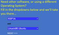
· Click on API.
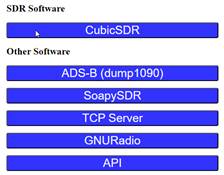
· Select API 3.07 and click on the blue button.
![]()
· Download the file SDRplay_RSP_API-Linux-3.07.1.run (or the latest one available).
· Make the file executable and then run it.
chmod +x SDRplay_RSP_API-Linux-3.07.1.run
./SDRplay_RSP_API-Linux-3.07.1.run
· Press ENTER to view the license agreement, view all and then press y.
· Press y to add SDRplay USB IDs to the local database. You must get no errors.
· Connect RSP device to the USB connector.
· Run the command lsusb and check that you can see the RSP device in the list.
![]()
· In your home folder run the following commands:
git clone https://github.com/SDRplay/RSPTCPServer.git
cd RSPTCPServer
mkdir build
cd build
cmake ..
You must get no errors
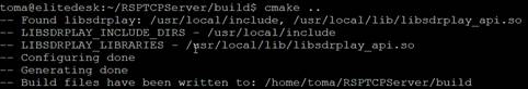
· Continue with:
make
sudo make install
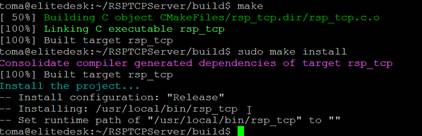
· If the RSP device is connected to the Linux PC where jAReC5 runs, copy the file /usr/local/bin/rsp_tcp to the addons subfolder in jAReC5 spplication folder ($APP_FOLDER/data/addons).
NOTE: To find jAReC5 application folder on a Mac, check Help > About.
· Continue here to learn how to configure jAReC5 to use the SDRplay RSP device.
Installing rsp_tcp server on a Mac computer
nfortunately the official procedure from SDRplay does not work for me.
https://www.sdrplay.com/docs/SDRplay_RSP_TCP_Server_Guide.pdf
Use the following steps.
· Install MacPorts on your Mac following the procedure described here, based on your MacOS version.
· Instal rsp_tcp server using MacPorts.
NOTE: As SDR library is not available yet for arm64 (M1/M2 Macs), if you want to install from MacPorts, you must first uncomment the following line in /opt/local/etc/macports/macports.cfg file
build_arch x86_64
· Now install rsp_tcp package with all dependencies using the following command. Only x86_64 version will be installed.
sudo port install rsp_tcp
· If the RSP device is connected to the Mac where jAReC5 runs, copy the file /opt/local/bin/rsp_tcp to the addons folder in jAReC5 ($APP_FOLDER/data/addons).
· Continue here to learn how to configure jAReC5 to use the SDRplay RSP device.
Configure jAReC5 to connect to the rtl_tcp/rsp_tcp server
First be sure that rtl_tcp/rsp_tcp server runs on the computer where the RTLSDR/RSP1A device is connected. To install and configure rtl_tcp server, follow the instructions according to the table below.
Follow the below steps. Steps order is important, so please do not change actions order, otherwise some steps may be required to be repeated.
· Define a new application profile. If you start the application for the first time, you will be automatically prompted to create a new profile. If not, you can do it from the startup page File > New Profile menu.
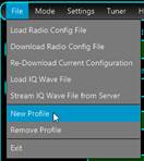
· Enter a profile name (ex. rtlsdr1). The number of characters for the profile name is not limited, but if it is too long, will be displayed truncated in the profiles list combo box. Click OK.
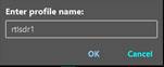
· You will be prompted for a filename for the profile file (*.prf4). Enter a filename (can be the same as the profile name, ex. rtlsdr1). Do not modify the default location for the profile file (.\data\profiles).
Click on Save button.
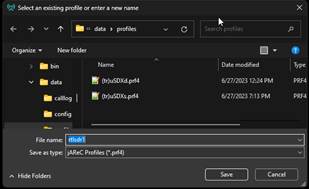
· The new profile name will be automatically selected in the profile combo box.
![]()
· Select Mode > Direct control.

· Download RSPTCP/RTLTCP radio configuration file from the central repository. Click on File > Download Radio Config File.
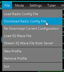
· Select from the list RTLSDR as brand and RTLTCP as model (for rtl_tcp server) or RSPTCP (for rsp_tcp server) and click Download.
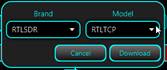
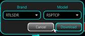
· You will get a preconfigured form. Some fields are automatically set: CAT Serial Port (None), Baudrate (None), Tx radio and headset audio (None, as this is a receiver only mode), Radio Rx audio interface to RTLSDR.
Headset icon will start flashing.
![]()
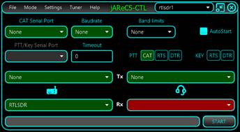
· Select headset Rx interface. Headset icon will stop blinking and the selected Rx headset interface will be green.
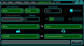
· From the Settings menu click RTLSDR socket.
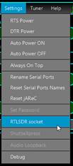
· Enter the IP address or hostname of the rtl_tcp/rsp_tcp server followed by “:” and then the tcp port on which rtl_tcp/rsp_tcp server is listening and click OK.
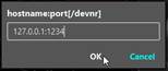
· By default, jAReC will try to connect to the first available RTRLSDR (default 0) or RSP device (default 1). If you have multiple RTLSDR/RSP connected to the same PC, then add after the port number a ‘/’ followed by the devnr. This is optional. For example, if device number 2 is used, enter:
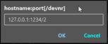
This allows you to connect to multiple RTL/RSP dongles using separate profiles.
· If the hostname/ip address is localhost or 127.0.0.1, jAReC5 will try to automatically start a local instance of rtl_tcp/rsp_tcp from the addons subfolder (if the required files exist in that folder).
Check one of the following links for RSP/RTL dongles and Windows/Linux/Mac.
· Click on START button to open main radio window. If you miss one of the steps above, you may not be able to go further and you will get an error message in the status bar.
![]()
· Main radio window will show in the top bar the current radio configuration file and timestamp. Click on CONNECT button to start operating the radio.
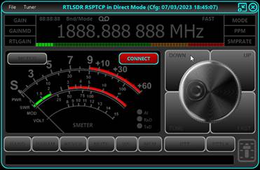
· Click on CONNECT button to connect to start the connection to the rtl_tcp/rsp_tcp server.
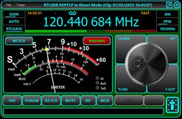
· Click on WF to start the open waterfall and audio spectrum windows.
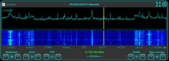
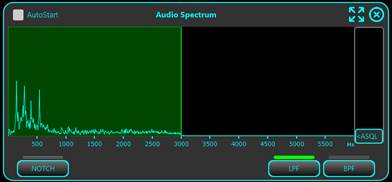
To learn how to operate the waterfall click here. For audio DSP, click here.
Some specific parameters are available for RTL/RSP mode only.
· GAIN – is an user adjustable gain for the IF block of the SDR engine
· GAINMD – RTL/RSP dongle gain mode (AUTO/MANUAL)
· RTLGAIN – RTL/RSP dongle RF GAIN (0-60dB), command send directly to the dongle
· PPM – used to calibrate the receiver (mostly for the RTL dongles, with significant frequency deviation). Values can be between -10 and 100.
· SMPRATE – sample rate for the SDR receiver. Current supported values are 256KHz, 512KHz, 1024KHz and 2048KH.
NOTE: In the current version, GAIN value has impact on the SMETER readings. You can calibrate the SMETER for a specific GAIN level by adjusting CALIB_SMETER line in the radio configuration file (see here for more details), but you can use the SMETER only to compare the level of different signals, not to display the absolute value of the received signal.
Using jAReC5 with a radio with IQ output (Malahit DSPx)
When you connect the radio through the microUSB cable to a PC/Mac, you will get a virtual COM port named Malahit DSP CAT.
![]()
and 3 audio devices, named Malahit Headphone, Malahit RX and Malahit IQ.
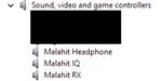
The COM port will be used for CAT and Malahit IQ audio device for IQ input.
Create a new profile File > New Profile, named for example MALAHIT.
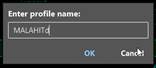
Save the new profile using an intuitive name., like for example malahitd (‘d’ from direct control).
Select Mode as Direct Control.
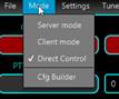
Download the radio configuration file clicking File > Download Radio Config File
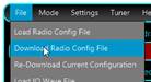
Select MALAHIT as brand and DSP2IQ as model and click on Download button.
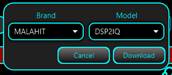
Set the other parameters from the graphical interface as in the picture below.
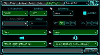
COM2 is the virtual serial port used for CAT.
NOTE: On some Windows PCs , it may be possible that Malahit IQ audio device is not available in the list. If this is the case, go (ex. in Windows 11) to System Sound Settings > Advanced > All sound devices.
It may be a different location for another Windows version.
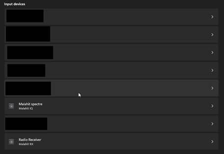
Click > for the Malahit spectre (Malahit IQ) device and click on Allow button (button label will change to Don’t allow).
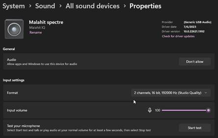
Check that Format is 2 channels, 16bit, 192000 Hz. Now the new device must be available in jAReC.
You can now click on START button, then CONNECT and operate the radio from jAReC.
You can adjust the gain for the Malahit IQ input directly in jAReC, as described here.
NOTE: As in this mode jAReC internal SDR engine is used, frequency on the MALAHIT DSPx display will not change when tuning in the spectrum area. Mode will not change at all, as demodulation is done in jAReC, not in Malahit.
Playing IQ Wave files
With jAReC5 you can play local or remote IQ files (available through HTTP/HTTPS).
First create a new profile as explained here.
Playing local IQ files
Go to File > Load IQ Wave File
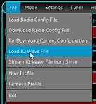
Select an IQ wave file from the local filesystem. Standard format for the filename to get maximum functionality is the following:
SDRuno_20230219_174615Z_3639kHz.wav
SDRuno – the name of the application that was used to record the IQ file (can be any non-empty string, as currently is not used)
20230219 – date of the record (using the format YYYMMDD)
124615Z – time of the record (using the format HHMMSS) and with a ‘Z’ at the end.
3639kHz – central frequency (in KHz).
If time is missing, you will not be able to see the UTC clock for the recording. If frequency is missing, 10000KHz (10MHz) will be used as default. After you load the local file, the app will try to extract more info from the file content, like Samplerate and Bits/sample. Click OK.
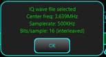
Most of the parameters will be automatically filled, except Headset playback device, that you must select manually.
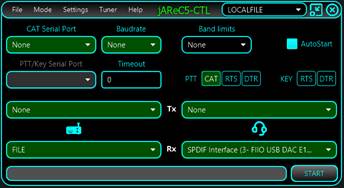
Now you can operate using jAReC5 internal SDR engine.
When you open the waterfall, if the timestamp is available in the wave filename, you will see the time at the moment of the recording in the upper left side. This is updated for the whole duration of the recording.
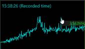
Playing remote IQ files
After you create a new profile as described here, go to File > Stream IQ Wave File from Server.
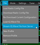
By default, the address of s web page hosted on my server will be shown.
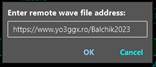
This page contains a set of recordings made during the Balchik 2023 80m band contest in March 2023. You can host your own files and modify this link accordingly. This link is defined in the associated radio configuration file named iq_file.radio4. The parameter is named IQSERVER.
In the local iq_file.radio4 file replace IQSERVER=https://www.yo3ggx.ro/Balchik2023 with your own link. The HTML page must have the following simple format (my page as an example).
<title>BALCHIK-WAVES-FRIENDS, edition 2023</title>
<body>
<h1>BALCHIK-WAVES-FRIENDS, edition 2023</h1>
<li><a href=SDRuno_20230311_145716Z_3653kHz.wav>Start at 14:57:16 UTC</a>(2,147,469,528)</li>
<li><a href=SDRuno_20230311_151510Z_3653kHz.wav>Start at 15:15:10 UTC</a>(2,147,469,528)</li>
<li><a href=SDRuno_20230311_153304Z_3653kHz.wav>Start at 15:33:04 UTC</a>(2,147,469,528)</li>
<li><a href=SDRuno_20230311_155058Z_3653kHz.wav>Start at 15:50:58 UTC</a>(2,147,469,528)</li>
<li><a href=SDRuno_20230311_160852Z_3653kHz.wav>Start at 16:08:52 UTC</a>(2,147,469,528)</li>
<li><a href=SDRuno_20230311_162646Z_3653kHz.wav>Start at 16:26:46 UTC</a>(2,147,469,528)</li>
<li><a href=SDRuno_20230311_164440Z_3653kHz.wav>Start at 16:44:40 UTC</a>(2,147,469,528)</li>
<li><a href=SDRuno_20230311_170234Z_3653kHz.wav>Start at 17:02:34 UTC</a>(2,147,469,528)</li>
<li><a href=SDRuno_20230311_172028Z_3653kHz.wav>Start at 17:20:28 UTC</a>(2,147,469,528)</li>
<li><a href=SDRuno_20230311_173822Z_3653kHz.wav>Start at 17:38:22 UTC</a>(2,147,469,528)</li>
<li><a href=SDRuno_20230311_175616Z_3653kHz.wav>Start at 17:56:16 UTC</a>(1,155,969,240)</li>
<h5>March 11, 2023 - Recordings by Dan (YO3GGX) using SDRuno and a RSP-1A receiver.</h5>
</body>
</html>
Click on OK to load the IQ wave files list from that page.
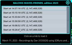
Click on a file you want to use. The file is not downloaded locally, it will be just streamed from the server.
Most of the parameters will be automatically filled, except Headset playback device, that you must select manually.
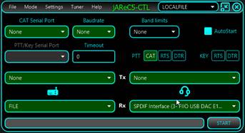
NOTE: Please take care that both RTS and DTR keying to be disabled before clicking on START.
Now you can operate using jAReC5 internal SDR engine.
When you open the waterfall, if the timestamp is available in the wave filename, you will see the time at the moment of the recording in the upper left side. This is updated for the whole duration of the recording.
SWR measurement
This feature is available in both Client and Direct Control modes. From the main radio window, when connected to the radio, click on Tuner > Scan SWR. A new window will open on top of the radio window.
NOTE: You cannot use this feature before defining IARU limits first. This is to prevent transmitting outside assigned HAM bands. Check here to learn how to set band limits.
During SWR scan, TX power is reduced, and mode changed according to the settings from Other parameters in the tuner section here.
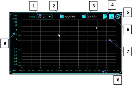
The interface has the following components:
1 – Select the number of measurements points.
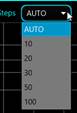
2 – If checked, the SWR scan is performed +/- 20KHz from the currently tuned frequency. This can be useful if you use a narrow band antenna (ex. Magnetic Loop). If unchecked, the full selected band is scanned (based on ITU selection).
3 – Some radios (like iCOM) allow you to change the frequency during TX using CAT commands. If this is the case with your radio, you can check “QSY in Tx”. This will allow a much faster scan for the selected band.
NOTE: You can try it anyway. If this is not supported, you will see that the frequency on the radio is not changed during scan, so you will be forced to uncheck it.
4 – Click on PLAY button to start scanning the SWR.
5 – Click on this button to close SWR scan window.
6 – Click on STOP button to force stop scan, without waiting for the full scan.
7 – Evolution of SWR across the band is displayed here.
8 – Frequency scale.
9 – SWR scale.
This is a sample scan for a fallen EFHW antenna helped by the IC7300 internal ATU, on 20m band tuned on 7MHz.
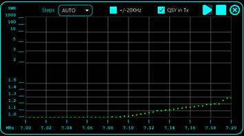
Cfg Builder
Configuration Builder is an integrated graphic tool used to build/edit/test radio configuration files. If you are not very familiar with the syntax used for the configuration files (described here), it is recommended to use this tool instead of directly editing the files.
Before entering Cfg Builder, you must configure the connection to the radio in Direct Control mode, as described here.
Click on Mode > Cfg Builder in the main application screen.
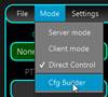
The following panel is displayed after you click on CONNECT button.
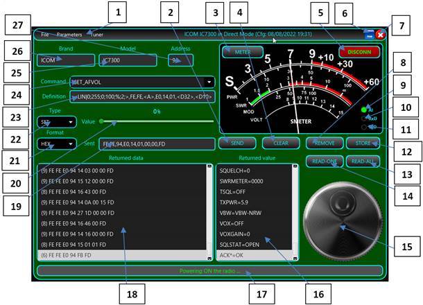
NOTE: If you enter Cfg Builder before downloading or opening a radio configuration file, all fields will be empty.
1 – Configuration Builder menu bar. File menu
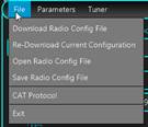
For File>Download … and File>Re-Download … and File>Open … options please refer to the documentation here.
File>Save Radio Config File is used to save the configuration file after you edit it. When saving the file, this is rebuilt with all definitions in alphabetical order, so even if you edit the file manually, at the end is a good idea to load it into the Cfg Builder and then save it, to keep it in an ordered format.
File>CAT Protocol is used to access the web page containing the CAT protocol documentation for the current radio. This URL link is defined in the configuration file.
Click on File>Exit to exit Cfg Builder.
Parameters
> Other menu. This is used to define extra parameters for the radio.
The following form will be open. 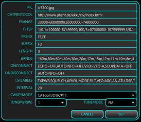
For more details about each parameter, check the radio configuration file description here.
Tuner menu. Please refer to description here.
2 – SEND button to send currently selected/created CAT command to the radio to test it.
3 – METER button selects what is displayed on the meter (for Rx or Tx). More details here.
4 – CLEAR button used to clear the content of the Returned data and Returned value fields.
5 – CONNECT button connects to the radio. When connected, the panel background will go dark green and the meter will light up.
6 – Click this button to minimize the Cfg Builder window.
7 – Click this button to close Cfg Builder.
8 – REMOVE button removes the currently selected command from the configuration file.
9 – Virtual AI (AutoInfo) LED, lights up when Auto Info is activated.
10 – Virtual Rx LED, which flashes when data is received from the radio.
11 – Virtual Tx LED, which flashes when data is transmitted to the radio.
12 – STORE button - used to store current command after you add it or have edited it.
13 – READ_ALL button reads from the radio all parameters which have a defined READ command. The result is displayed in the Returned data and Returned value fields.
14 – READ-ONE reads from the radio the value of the currently selected parameter (even if SET, PAT or CAL type are selected).
15 – Frequency tuning knob, used to test fine tuning commands.
16 – If the received raw data from the radio contains a valid defined parameter value, it is interpreted and displayed in this field. If the received data is not valid, but it is for a valid parameter, ‘parname=?’ is displayed. If the parameter cannot be determined from the received data, ‘?=?’ is displayed here.
17 – Status bar - used to display informational or error messages during Cfg Builder operation.
18 – Raw data as received from the radio is displayed in this field in the selected format as defined in the pull-down options under (20).
19 – Once the command is built from a definition, what will be sent to the radio is displayed here in RAW format.
20 – If the parameter has an analog value, a slider is used to set the parameter value. If the parameter has discrete values, a combo box is used to set the desired value.
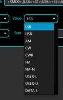
21 – This combo box selects the format to be used for the Sent and Returned data fields. Some radios use a string-based (STR) protocol (including Yaesu FT450, 991, etc. & Kenwood), or a byte based (HEX) protocol (Yaesu FT8x7, most if not all, ICOMs). For some radios (like FT8x7) you may also need a binary representation (BIN), as some parameters are assigned to specific bits.

22 – This combo box is used to select the parameter definition section: SET (for the SET commands), READ (for the read commands), PAT (for the radio’s layout or pattern of returned data) or CAL (for calibration data, used with the meter displays).
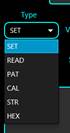
23 –This is the definition (pattern) of the current command, using the standard syntax. Check your radio configuration file format here for more details.
24 – Combo box containing the list of already defined commands.
NOTE: For each parameter, all 3 definitions must exist (SET, READ and PAT), even if for some parameters, READ and PAT are empty (no read command available, only SET command).
25 – The radio model is displayed here.
26 – The radio Brand is displayed here.
27 – Radio address. This field is only visible for iCOM and other CI-V protocol compatible radios.
Connecting to the radio
When you connect to the radio from the Cfg Builder all defined parameters are automatically read from the radio. The two lists (data and value) are kept in sync. If you click on any item from one of the lists, the corresponding item from the other list is selected too.
You can scroll through the Returned data and Returned value lists to check in case for a parameter there is a value returned that cannot be decoded.
NOTE: In the example above, the returned data ‘3F3B’ (second line down) is a Yaesu “command not ok” message for one of the commands sent. There are some situations in which requested parameters cannot be read. In this particular case, the RFGAIN parameter cannot be read because the radio is set to use SQUELCH at the moment instead of RFGAIN (SQLRFGAIN=SQL). As jAReC continuously polls the radio during normal operation so that the parameters will be always kept synchronized between the radio and jAReC.
Creating a new command
To create a new command, select New from the end of the list of already defined commands (23). Type the command name in (23) and then write its definition in (22). When ready, click on STORE (11). To test the command, set the desired value for the parameter in (19) and click on SEND (2).
NOTE: If the Sent (18) field displays ‘?’, then the command definition is wrong, and the application is not able to build it. Do not click on SEND again if the definition is wrong. You must check the syntax again and correct it first.
Editing an existing command
To edit an existing command, select it from the list of already defined commands (23). Edit the command definition in (22). When ready, click on STORE (11). To test the command, set the desired value for the parameter in (19) and click on SEND (2).
NOTE: If the Sent (18) field displays ‘?’, then the command definition is wrong and the application is not able to build it. Do not click on SEND again if the definition is wrong. You must check the syntax again and correct it.
Displaying data received from the radio
Depending on the protocol used by the radio, select the correct data format in (21). For each SET command, the radio returns a confirmation message or an error indication. Currently this data is not used in normal operation but can help you debug your changes and additions to the configuration file. When you send a READ command, the radio returns the parameter value in a format specified in the CAT protocol in the Returned data field.
This is an example of data returned by a Yaesu FT450 for a READ_MODE command, in STR (string) format mode.
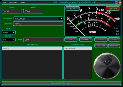
Some commands may return multiple answers. In the following example, reading the mode value (CW) will return the currently selected filter value (FLT1) too (ICOM IC7300).
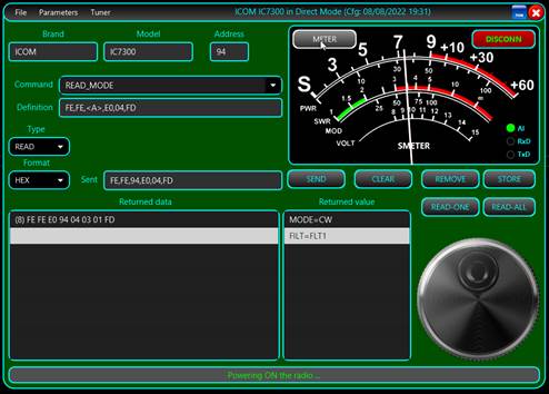
Radio configuration file
The radio configuration file contains several sections that will be described below. jAReC can support 3 main radio protocol categories:
· String based protocol - variable length, both prefix and suffix used for both sent and received data. (Yaesu FT450, FT950, FT991, Kenwood, etc.)
· Variable length hex-based protocol – byte-based data, both prefix and suffix used for both sent and received data. (ICOM radios)
· Fixed length hex-based protocol – byte-based data, no prefix and no suffix used. (Yaesu FT8x7 radios)
General section
Here you define specific parameters for the radio. This sample is from a Yaesu FT450 config file. Some parameters are self-explanatory. Most of the parameters are commented inside the configuration file.
; **** Generic section ****
TIMESTAMP=07/16/2023|12:45:07 <- this timestamp is generated when you save the config file from Cfg Builder.
VERSION=4 <- configuration version (not compatible with v3)
BRAND=YAESU
MODEL=FT450
PIC=FT450.jpg
SIGRADIOS=$1gG49@A10XsG
; Device Mode <- New in v5
; 1 - standard CAT, no decoding inside this app, possible waterfall through serial CAT (ex. IC7300, IC705), audio DSP
; 3 - audio IQ based radios (Malahit DSP, SoftRock, etc.), decoding inside this app, CAT commands still supported for special functions
; 4 - RTLSDR or RSP1A devices over standard rtl_tcp/rsp_tcp
; 5 - RSP devices over extended rsp_tcp
; 6 - IQ wave file (local or remote through http(s)
; 7 - (tr)uSDX, use audio in/out over serial port
DEVICEMODE=1 <- if this parameter is missing, 1 (standard CAT) will be considered by default
; Rx only mode <- New in v5
; 0 - default, both Rx and Tx
; 1 - Rx only (PTT disabled)
RXONLY=0 <- If this parameter is missing, 0 (Both Rx and Tx) will be used by default
; Location for the CAT protocol documentation (HTML or PDF file)
CATPROTOCOL=https://www.yaesu.com/downloadFile.cfm?FileID=13311&FileCatID=158&FileName=FT-450D_CAT_OM_FENG_1710-B.pdf
; Radio Address (used only for iCOM radios)
; Hexa format (2 chars)
RADIOADDRESS= <- ex. for IC7300 is RADIOADDRESS=94
; Frequency coverage, in Hz, sections separated by ','
; format: FRANGE=f1-f2,f3-f4,f5-f6,...
FRANGE=30000-56000000 <- ex. for IC7300 is FRANGE=30000-60000000,65000000-74800000
; Frequency step per frequency range, in KHz, freq range in Hz
; format: FSTEP=<brute_step1>/<fine_step1>=<freq_interval1_min>-<freq_interval1_max>,<brute_step2>/<fine_step2>=<freq_interval2_min>-<freq_interval2_max>, ...
; brute for +/-, fine for knob tuning
FSTEP=0.1/0.01=100000-87499999,100/5=87500000-107999999,1/0.01=108000000-136999999,25/0.01=137000000-137995000,6.25/0.01=138000000-173999999,25/0.01=174000000-215999999,12.5/0.01=216000000-224999999,12.5/0.01=225000000-469999999,25/0.01=470000000-1300000000
; CAT command / radio answer prefix (in standard command format), empty string if none
PREFIX= <- ex. for IC7300 is PREFIX=FEFE
; CAT command / radio answer suffix (in standard command format), empty string if none
SUFFIX=3B <- this is ‘;’ char, for IC7300 is SUFFIX=FD
; Command / radio answer length (in bytes), if fixed length, 0 if variable length
LENGTH=0 <- ex. for FT817 is LENGTH=5
; Interval (in ms) between successive commands sent to the radio. Usual is 0, but with some radios a bigger delay may be required to prevent overlapping answers.
INTERVAL=0 <- most of the radios will use 0 for this parameter
; TXPWR used by the application during the tuning and SWR scan processes.
TUNEPWR=10
; MODE used by the application during the tuning and SWR scan processes.
TUNEMODE=FM
; Serial Interface, pin used and mode (PTT must be on or off during keying) for CW keying .
; 0=PTTcom/DTR/NOPTT
; 1=PTTcom/RTS/NOPTT
; 2=CATcom/DTR/NOPTT
; 3=CATcom/RTS/NOPTT
; 4=PTTcom/DTR/PTT
; 5=PTTcom/RTS/PTT
; 6=CATcom/DTR/PTT
; 7=CATcom/RTS/PTT
CWKEY=1 <- this mean RTS line over PTT serial port is used for
Keying, PTT not required to be activated before keying.
; List of available Bands
BANDS=160m,80m,40m,30m,20m,17m,15m,12m,11m,10m,6m
; Parameters(s) to be set when connected/disconnected to/from the radio (ex. commands to control external devices, PSUs, antennas, etc.)
; format param1=value1,param2=value2,...
; you can add as a command a pause in the standard format PAUSE=xxxx
; 'paramx' can be any of the radio parameters (including script names)
; if POWER=ON is used, then this must be in the first position
; example:
; ONCONNECT=FREQ=3705000,MODE=LSB,<P1000>,AFVOL=50
ONCONNECT=POWER=ON,VFO=VFO-A,CLAROFF=0
ONDISCONNECT=POWER=OFF
; Waterfall section (only for supported radios)
WFON=SCOPE=ON,EDGE=EDGE1,VBW=VBW-NRW,SCOPEREF=0,SCOPDATA=ON,SCOPMODE=SCP-FIX,SCOPESPD=WF-FAST <- a list of CAT commands required to start the waterfall streaming over CAT
WFOFF=SCOPDATA=OFF <- a list of CAT commands required to stop the waterfall streaming over CAT
; List of all SET/READ/PAT(tern)/CAL(ibration) parameters
LSTPARAMS=TXPWR,ATT,PAMP,MODE,VFO,RFGAIN,ACK*,AFVOL,AGC,ALCMETER,AN,ATU,AUTOINFO,BKIN,BRIGHT,CMPLVL,COMPRESS,CWPITCH,CWSPEED,DSP,ECHO,EDGE,FILT,FREQ,FREQ*,LOCK,MICLEVEL,MODMETER,MODE*,MONITOR,MONLEVEL,NB,NBLEVEL,NOTCH,NOTCHLVL,NR,NRLEVEL,POWER,PTT,PWRMETER,RIT,RITFREQ,RTONE,SMETER,SCOPE,SCOPDATA,SCOPMODE,SCOPEREF,SCOPESPD,SPLIT,SQLSTAT,SQUELCH,SWRMETER,TSQL,USBCW,USBPTT,VBW,VLTMETER,VOX,VOXGAIN,WFBW <- as of version 5, first 6 parameters from this list will be displayed directly in the graphical interface, on the left and right part
of the frequency display. The rest are available through he Parameters panel
Commands definition syntax (TAGs)
Each command has the following format: cmdtype_paramname=byte1,byte2,... where cmdtype can be SET,READ,PAT(pattern) or CAL(calibration).
NOTE: For a specific parameter/setting, paramname must be identical for all SET, READ, PAT and CAL sections !!!
List of available TAGs:
Bytes represented as hex values
xx,xx,... - bytes represented as hex values, separated by commas.
Bytes represented as binary values
{10010110} - a binary represented byte
Radio address
<A> - replaced with radio address as one byte
A string
<Sabcdef> - string 'abcdef' (one byte generated per char)
A char digit
<Cx> - 'x' order digit, from 0 to F (15) - frequency up to 1000THz supported, one byte
Two digits packed in a byte (BinaryCodedDecimal)
<Dxy> - 'x' and 'y' digit order - 2 BCD packed digits in the same byte, from F(1000THz) To 0(Hz)
Delay (pause) between 2 bytes
<Pxyzu> - add a 'xyzu' ms delay between 2 consecutive bytes
Bytes based on parameter value
{name1=hex1;name2=hex2; ...} - For each named parameter value (name1, name2, etc.), set the byte with the corresponding hexadecimal value (hex1, hex2, etc.).
Example (FT450):
{OFF=<S0>;FAST=<S1>;SLOW=<S3>;AUTO=<S6>;}
If the value is OFF, the byte is the ASCII code of ‘0’ char, if the value is FAST, the byte is the ASCII code of ‘1’ char, etc.
You can have SET commands affected by other parameters. For example, SET_MODE for IC7300 radios is dependant on FILT parameter as well. Then add this as a suffix for the byte of the parameter name followed by ‘:’.
SET_MODE=FE,FE,<A>,E0,06,{MODE:LSB=00;USB=01;AM=02;CW=03;RTTY=04;FM=05;CWR=07;RTR=08;},{FILT:FLT1=01;FLT2=02;FLT3=03;},FD
This is another example for FT450. The format of the SET_FREQ command depends upon the currently selected VFO.
SET_FREQ=<SF>,<VFO:A='A';B='B';>,<C7>,<C6>,<C5>,<C4>,<C3>,<C2>,<C1>,<C0>,<S;>
Linear parameters represented as one or multiple bytes
<LIN|val0;val1;val2;val3;M;stp;>
Where:
· val0 = min value to be sent to the radio
· val1 = maximum value to be sent to the radio
· val2 = minimum parameter value
· val3 = maximum parameter value
· M = measuring unit (W,Hz,%,etc.)
· stp=change step
Example for Tx power from 1 to 100W, but value to be sent is between 0 and 255: SET_TXPWR=<LIN|5;100;5;100;W;1;>,<SEX048>,<C2>,<C1>,<C0>,<S;>
Simplified format commands
For some internal commands (used especially with the embedded SDR decoding engine), the format is simplified.
Ex.1
SET_GAIN=(0*100|40|none|1)
0*100 – interval for the parameter (0-100)
40 – initial value for the parameter
none – unit for the parameter (as a string, ex. Hz, %, etc)
1 – variation step for the parameter
Ex.2
SET_MODE=(LSB,USB,CW,AM,FM,WFM|LSB|none|none)
LSB,USB,CW,AM,FM,WFM – list of parameter discrete values
LSB – initial value
none - unit for the parameter
none - variation step for the parameter
Custom scripts
Custom commands (scripts to be executed on the operating system where jAReC is running) are defined like any other CAT command, using the following format:
SET_SCRIPTNAME=[full_path_to_the_executable_name and parameters, if any]
Replace '\' with '\\' in the file path for Windows systems
Include command in ' " ' if contains spaces
Example to start Notepad:
SET_JAVAVER=["C:\\Windows\\notepad.exe"]
Returned value (if any) will be displayed as a toast message.
Writing data to EEPROM locations (Yaesu FT8x7)
<WEaddr;xxxxxx11;xxxxxxxx;>
Where:
· addr is the EEPROM address to write to (2 bytes). 2 consecutive EEPROM locations are written with a single SET command.
· ‘x’ - the bits that must remain unchanged.
· ‘1’ - the bits that depends on the parameter value.
Example:
SET_AGC=<WE0057;xxxxxx11;xxxxxxxx;>,{AUTO=00;FAST=01;SLOW=10;OFF=11;}
Reading data from an EEPROM location (Yaesu FT8x7)
<REaddr>
Where:
· addr is the EEPROM address to write to (2 bytes). 2 consecutive EEPROM locations are read with a single READ command.
Example:
READ_AGC=<RE0057>
Multiple definitions for the same parameter
You can add multiple definitions for a specific parameter (ex. ICOM patterns for MODE, FREQ). Keep the same parameter name and add one or more '*' at the end of the parameter name. One example where this is needed is when the data received back from the radio could be one or two bytes long e.g. 10 or 255.
Patterns definition syntax (TAGs)
Pattern definitions are similar to the corresponding SET command.
Simple analog value packed as a string (same as for the associated SET command)
PAT_AFVOL=<SAG0>,<C2>,<C1>,<C0>,<S;>
Simple analog value packed as two bytes
PAT_AFVOL=FE,FE,E0,<A>,14,01,<D32>,<D10>,FD
Simple discrete values parameter received as a string
PAT_AGC=<SGT0>,{<S0>=OFF;<S1>=FAST;<S3>=SLOW;<S6>=AUTO;},<S;>
Multiple parameter values received in a single string
PAT_FREQ=<SF>,{VFO:<SA>=VFO-A;<SB>=VFO-B;},{FREQ:<C7><C6><C5><C4><C3><C2><C1><C0>;},<S;>
Multiple parameter value possibilities received in a byte based answer
PAT_FILT=FE,FE,XX,<A>,04,{MODE:00=LSB;01=USB;02=AM;03=CW;04=RTTY;05=FM;07=CWR;08=RTR;},{FILT:01=FLT1;02=FLT2;03=FLT3;},FD
Binary packed parameters value (in 2 bytes)
For an EEPROM read command, two bytes are always returned from two consecutive EEPROM addresses.
Example:
<B;5x43x211;87xxxx66;1:AGC;2:DISPLAY;3:PBT;4:NB;5:FST;6:METERSEL;7:VMETER;8:VOX;>
<B; - a binary byte definition
Here in the two bytes, we represent the bits that contain parameters value with digits and use ‘x’ for bits that can be discarded.
The number received in a bit can be further described, in text, in the pattern statement.
A parameter value can occupy one or more bit.
Multiple parameter values and formats in the data received from the radio after a read command is issued
Example: Reading frequency and mode with a single command
{FREQ:<D87><D65><D43><D21>;} - 4 bytes
{MODE:00=LSB;01=USB;02=CW;03=CWR;04=AM;08=FM;0A=DIG;0C=PKT;} - 1 byte
Set command section
Here are some sample ‘set’ commands for different radios, to help you better understand how can you set different parameters using the syntax defined here.
Yaesu FT450
Set AF volume
SET_AFVOL=<LIN|0;255;0;100;%;2;>,<SAG0>,<C2>,<C1>,<C0>,<S;>
Set AGC
SET_AGC=<SGT0>,{OFF=<S0>;FAST=<S1>;SLOW=<S3>;AUTO=<S6>;},<S;>
Set Frequency
SET_FREQ=<SF>,{VFO:VFO-A=<SA>;VFO-B=<SB>;},{FREQ:<C7><C6><C5><C4><C3><C2><C1><C0>;},<S;>
Set Clarifier Offset (RIT)
SET_CLAROFF=<LIN|-9999;+9999;-9999;+9999;Hz;10;>,<SRC;R>,{+=<SU>;-=<SD>;},<C3>,<C2>,<C1>,<C0>,<S;>
Set IF Shift
SET_IFSHIFT=<LIN|-1000;1000;-1000;1000;Hz;10;>,<SIS0>,{+=<S+>;-=<S->;},<C3>,<C2>,<C1>,<C0>,<S;>
Set Power
SET_POWER=<SPS>,{OFF=<S0>;ON=<S1>;},<S;>,<P100>,<SPS>,{OFF=<S0>;ON=<S1>;},<S;>,<P500>,<SPS>,{OFF=<S0>;ON=<S1>;},<S;>,<P1000>
ICOM IC7300
Set AF volume
SET_AFVOL=<LIN|0;255;0;100;%;2;>,FE,FE,<A>,E0,14,01,<D32>,<D10>,FD
Set AGC
SET_AGC=FE,FE,<A>,E0,16,12,{AGC-F=01;AGC-M=02;AGC-S=03;},FD
Set Frequency
SET_FREQ=FE,FE,<A>,E0,05,<D10>,<D32>,<D54>,<D76>,<D98>,FD
Set RIT frequency
SET_RITFREQ=<LIN|-9999;+9999;-9999;+9999;Hz;10;>,FE,FE,<A>,E0,21,00,<D10>,<D32>,{+=00;-=01;},FD
Set Filter
SET_FILT=FE,FE,<A>,E0,06,{MODE:LSB=00;USB=01;AM=02;CW=03;RTTY=04;FM=05;CWR=07;RTR=08;},{FILT:FLT1=01;FLT2=02;FLT3=03;},FD
Yaesu FT817
Set AGC
SET_AGC=<WE0057;xxxxxx11;xxxxxxxx;>,{AUTO=00;FAST=01;SLOW=10;OFF=11;}
Set Frequency
SET_FREQ=<D87>,<D65>,<D43>,<D21>,01
Set Band A
SET_BAND-A=<WE0059;xxxx1111;xxxxxxxx;>,{160m=0000;80m=0001;40m=0010;30m=0011;20m=0100;17m=0101;15m=0110;12m=0111;10m=1000;6m=1001;FM=1010;AIR=1011;2m=1100;70cm=1101;PHANTOM=1110;}
Set Clarifier Frequency
SET_CLARFREQ=<LIN|-9999;+9999;-9999;+9999;Hz;10;>,{-=01;+=00;},00,<D32>,<D10>,F5
Read commands section
Read commands are very simple, and require no additional parameters, using the syntax defined here.
Some examples for clarification:
Yeasu FT450
READ_CWSPEED=<SEX021;>
ICOM IC7300
READ_AGC=FE,FE,<A>,E0,16,12,FD
Yaesu FT817
READ_AGC=<RE0057>
READ_FREQ=00,00,00,00,03
Patterns definition
Some examples for the 3 main protocol types.
Yaesu FT450
AF volume – simple linear value
PAT_AFVOL=<SAG0>,<C2>,<C1>,<C0>,<S;>
AGC mode – discrete parameter values
PAT_AGC=<SGT0>,{<S0>=OFF;<S1>=FAST;<S3>=SLOW;<S6>=AUTO;},<S;>
IF Shift – analog value with sign
PAT_IFSHIFT=<SIS0>,{<S+>=+;<S->=-;},<C3>,<C2>,<C1>,<C0>,<S;>
ICOM IC7300
RIT Frequency – analog value with sign
PAT_RITFREQ=FE,FE,E0,<A>,21,00,<D10>,<D32>,{00=+;01=-;},FD
AGC mode – discrete parameter values
PAT_AGC=FE,FE,E0,<A>,16,12,{00=OFF;01=AGC-F;02=AGC-M;03=AGC-S;},FD
AF volume - analog simple value
PAT_AFVOL=FE,FE,E0,<A>,14,01,<D32>,<D10>,FD
Yaesu FT817
This is the most complex format for a pattern. Multiple parameters values can be received in a single byte, so a binary pattern is used.
AGC pattern
PAT_AGC=<B;5x43x211;87xxxx66;1:AGC;2:DISPLAY;3:PBT;4:NB;5:FST;6:METERSEL;7:VMETER;8:VOX;>,{AGC:00=AUTO;01=FAST;10=SLOW;11=OFF;},{DISPLAY:0=OFF;1=ON;},{PBT:0=OFF;1=ON;},{NB:0=OFF;1=ON;},{FST:0=OFF;1=ON;},{METERSEL:00=PWR;01=ALC;10=SWR;11=MOD;},{VMETER:0=OFF;1=ON;},{VOX:0=OFF;1=ON;}
Calibration definition
For each meter you must define calibration data based on returned data from the radio after a READ command. If the returned value represents the final data, then the respective meter calibration data is empty. Calibration is done using a limited number of calibration points. The rest of the values are interpolated by the application.
The format for the calibration data for each calibration point is:
returned_data=real_data;
A special situation exists for the S-METER, where the values between S1 and S9 are represented as 100, 200, … 900. Values over S9 (+10dB .. +60dB) are represented as 910, 920, …, 960.
The following calibration definitions must exist in each config (even if some are not used for a specific radio):
CAL_ALCMETER
CAL_MODMETER
CAL_PWRMETER
CAL_SMETER
CAL_SWRMETER
This is an example (for the Yaesu FT450):
CAL_ALCMETER=0=0;120=100;
CAL_MODMETER=
CAL_PWRMETER=0=0;74=10;107=20;132=30;148=40;164=50;181=60;197=70;206=80;222=90;245=100;
CAL_SMETER=0=0;16=100;41=200;58=300;74=400;90=500;107=600;118=700;137=800;156=900;173=910;189=920;206=930;222=940;238=950;255=960;
CAL_SWRMETER=0=1;66=2;120=3;200=10;
Parameter labels definition
Only the parameters that are presented in the LSTLABELS definition are displayed in the interface (a maximum of 38).
You can set the order in the GUI (from left to right and then wraps to a new line) by the sequence that you list them in the LSTLABELS definition in the configuration file.
Macros definitions
Some radios can use the same command to read and/or set multiple parameters at once. In this case you can use macros, to simplify the configuration file and make it easier to do changes (in a single instead of multiple places).
For this, a dedicated section in the radio configuration file can be added (example for FT817).
; List of defined macros (start with '$Xnn=definition' where
; X - type of definition (S,R or P for SET/READ/PAT definitions
; nn - macro number (00-99)
; definition - macro definition
;
Then sections for SET, READ and PAT macros:
; SET Macros
$S00= …
…
; READ Macros
$R00= …
…
;PAT Macros
$P00= …
…
An example for a pattern Macro
$P00=<B;xxx12x33;xx456789;1:DW;2:PRI;3:TXPWR;4:UHFANT;5:VHFANT;6:AIRANT;7:FMANT;8:6MANT;9:HFANT;>,{DW:0=OFF;1=ON;},{PRI:1=OFF;0=ON;},{TXPWR:11=0.5W;10=1.0W;01=2.5W;00=5.0W;},{UHFANT:0=UHF-FRONT;1=UHF-REAR;},{VHFANT:0=VHF-FRONT;1=VHF-REAR;},{AIRANT:0=AIR-FRONT;1=AIR-REAR;},{FMANT:0=FM-FRONT;1=FM-REAR;},{6MANT:0=6M-FRONT;1=6M-REAR;},{HFANT:0=HF-FRONT;1=HF-REAR;}
And then define the READ commands for example as:
PAT_6MANT=$P00
PAT_AIRANT=$P00
PAT_FMANT=$P00
PAT_HFANT=$P00
PAT_VHFANT=$P00
PAT_UHFANT=$P00
Program history (staring with first v5 beta)
jAReC_v5.0_beta1_en.pdf Bucharest - Jul 30, 2023 – © Dan Toma – YO3GGX – yo3ggx@gmail.com