jAReC
(j)ava (A)udio and (Re)mote (C)ontrol
A Java multiplatform application used to remote control your transceiver locally (over serial/USB/Bluetooth) or over the network
Version 4.0
Dan Toma - YO3GGX - yo3ggx@gmail.com
Contents
Application folders and file structure’s
Displaying data received from the radio
Commands definition syntax (TAGs)
Patterns definition syntax (TAGs)
v4.0 – first public release (Dec 27, 2021)
Introduction
This is a multi-platform Java application which can be used to control your own CAT enabled transceiver (with support for audio) using a Serial/USB Serial/Bluetooth or network connection. jAReC can act as both a server and as a client. The PocketRxTx Android application can be used as a client securely to connect over the network and control (CAT) your radio transceiver remotely via jAReC server over the Internet or local LAN, with bi-directional audio support.
Features
The current version of the application has the following features:
· Can be run on Windows, Linux, or Mac.
· The application is self-contained and fully portable. It can even be run from a memory stick. Nothing is modified in the hosting operating system.
· You do not require to install a java runtime environment.
· Several configuration profiles can be set within jAReC. One for each mode of operation (direct control, client, or server mode) or for multiple transceivers connected at different times to the same computer where jAReC is installed. You can just load the saved profile you wish without having to reconfigure the application each time you change the operational mode or transceiver.
· You can select any local serial port (COMx in Windows, /dev/ttySx or /dev/ttyUSBx in Linux, etc).
· Serial ports can be named, so you can easily identify them afterwards.
· You can select Audio In and Audio Out devices from a list. The audio feature is bi-directional, with mic and speaker level indicators for better control.
· Two audio interfaces can be defined in direct control mode: one for radio audio and the other one for a local wired or wireless headset.
· The TCP port used for the remote connection is configurable. The same numbered UDP port is used for audio, if audio is activated.
· The Baud rate is configurable from 110 to 921600.
· Settings are saved in a configuration file and are loaded automatically the next time the program is started.
· The program can be automatically started allowing unattended mode operation.
· In server mode, the program auto disconnects if the network link is lost and goes back to “waiting for connection” status, without user intervention.
· When jAReC is being used to control a transceiver, PTT control can be done over CAT or through RTS or DTR signals, on the same serial port used for CAT controls or on a different one.
· There is a user configurable PTT timeout setting, to prevent PTT locking in Tx if the network link drops during transmission.
· Custom commands/scripts can be sent as CAT.
· A graphical configuration builder is included. This includes the facility to test different/modified CAT commands and then to create or edit a radio configuration file according to your own needs.
· The application includes call logging features, with QRZ.com integration for automatic filling of station details by querying the QRZ.com database. You need a valid free QRZ account for basic information (Name, QTH, Country), or a paid XML subscription to get all available information for the station being entered in the log.
· A CW Keyer is included, allowing you to send pre-entered CW messages. The speed is user adjustable. Up to 8 messages can be pre-defined.
· Internal and external tuners are supported, making the antenna tuning process much simpler. When triggered the desired TX mode and level is used for the tuning action.
· You can display the SWR graph across the currently selected band in up to 100 steps (currently only with selected transceivers supporting the change of frequency through CAT commands during Tx).
· Auto transceiver power on/off when connecting to the radio from jAReC (user selectable).
· Full support for Contour Design ShuttleXpress (without requiring extra drivers). You can control almost all radio functions through this device.
· Keyboard shortcuts are present for some of the main functions.
IMPORTANT!!!: jAReC v4 is backwards compatible with Pocket RxTx v3.x (when in Server-v3 mode), so jAReC v3 will become obsolete.
WARNING!!!
Use this application at your own risk. I cannot be held responsible for any damage caused to your system or transceiver by using this application.
Application folders and file structure’s
The application folder is considered to be the one from where the application is started. For the packaged versions this is the executable folder (bin subfolder). When you run the jar file directly through a script, it is the script folder.
The structure is the following:
App folder ---configs: jsn4.cfg(jAReC config file) and *.prf4 (profile files)
|
--- radio: *.radio4 (radio configuration files),*.jpg(radio pictures), radios.lst(list of available brands and models)
Starting the application
The application is distributed in multiple formats:
- A simple jar file (java runtime and javafx >= version 11 required to be installed previously on the system).
- A self-contained Windows package (require Windows 8 and up).
- A self-contained Linux package (tested on Ubuntu 20.04)
- A self-contained Mac package (tested on MacOS 11 and 12, but may work on previous versions too)
- To run the application on a Raspberry Pi you must install the required java packages and use the jar file directly (details can be found here).
Windows
The simplest way to run the application on Windows is to unpack jAReC_v4xx_Win_x64.zip in a folder on your PC and run the executable by just double clicking on jAReC.exe. (override all the Windows security warning – ie select “keep file” and similar options).
If you want to use the Java runtime that is already available on your system, then run jAReC with the following command from the folder where jAReC.jar file is:
%JAVA_HOME%\bin\java -jar --module-path %JAVA_FX%\lib --add-modules javafx.controls jAReC.jar
Replace %JAVA_HOME% with the folder where openjdk-jre is installed. Replace %JAVA_FX% with the folder where javafx is installed.
NOTE: Both openjdk-jre (version 11 or 14) and javafx (11 or 17) are required to run jAReC.
Linux (x64)
The simplest way to run the application on Linux (x64) is to unpack jAReC_v4xx_Lin_x64.zip in a folder on your PC and run the jAReC.command file.
NOTE: Please be aware that the packaged version is available only for the x64 architecture.
If you run Linux on another hardware architecture (ex. Raspbian or Raspberry Pi OS), then you must follow the steps below:
1. Install openjdk-jre using:
sudo apt install openjdk-11-jre
or
sudo apt install openjdk-11-jre-headless (Raspberry Pi)
2. Install javafx using:
sudo apt install openjfx
3. Note the folder where openjdk was installed, usually
/usr/lib/jvm/java-11-openjdk-amd64/
or
/usr/lib/jvm/java-11-openjdk-armhf/ (Raspberry Pi)
4. Note the folder where javafx was installed, usually
/usr/share/java/
5. Go to the folder where jAReC.jar file was downloaded and run the command (after adjusting the folders accordingly:
/usr/lib/jvm/java-11-openjdk-amd64/bin/java --module-path /usr/share/java --add-modules javafx.controls -jar jAReC.jar
Mac OS
To run the application on a Mac, unpack jAReC_v4xx_mac_x86_64.zip in a folder on your Mac and run the jAReC4.app file.
First application start
The application’s graphical interface will look absolutely the same on every operating system you are running it on. When you start the application for the first time or after a full application reset, you will be prompted to define a new application profile.
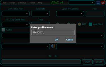
Enter a friendly name for the profile you want to create, for example FT450-CTL (direct control a FT450 transceiver), FT45-CLI (Control FT450 in client mode), or FT450-SRV (Control FT450 in server mode) and then press OK.
NOTE: You cannot start the application without defining a valid profile name.
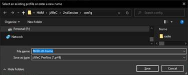
After giving a friendly name, you need to supply a filename for the new profile to be saved into, like ft450-ctl-home in the example below enter the filename and press Save.
Main Menu
Some of the menu items may not be available in all operation modes.
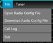
File Menu
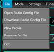
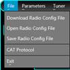
Open Radio Config File – Load a radio configuration file that is available locally.
Download Radio Config File – Download a radio configuration file from the central repository. You will be prompted to select radio brand and radio model from the dropdown lists.

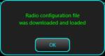
When ready, click on the Download button. You will receive a confirmation if the file is successfully downloaded.
New Profile – create a new application profile. The process is the same as described above under “First Application Start” (see here).
Remove Profile – remove currently selected application profile. If there is only one profile available, this cannot be removed.
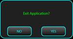
Exit – Exit application. You will be asked for confirmation.
Mode Menu
This is used to set the application mode. i.e. what jAReC will do.
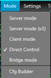
The format of the form displayed depends on the last selected operation mode (Server, Server(v3), Client, Direct Control or Bridge).
Direct Control
![]()
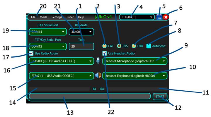
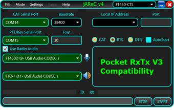
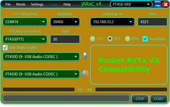
This is the screen displayed when Direct Control has been selected as operational mode.
1 – Timeout in seconds for the PTT. This is used to prevent the situation when the transceiver could remain in Tx mode after a connection lost.
2 – select this button so that PTT is sent via a CAT command.
3 – select this button so that PTT is sent using the RTS signal line (see 18 for serial port to be used for PTT).
4 – Name of currently selected configuration profile.
5 – Button used to minimize the form.
6 – Button used to exit the application.
7 – select this button so that PTT is sent using the DTR signal line (see 18 for serial port to be used for PTT).
8 – If checked, when the application is run it will start in the last selected mode of operation and not display this screen.
9 – Indicates the audio device to be used as input microphone.
10 – Indicates the audio device to be used as output earphone.
11 – Bar that shows the receiver audio level during Rx.
12 – Click this button once all relevant fields are entered to start the selected mode of operation.
13 – Status bar, used to display different program messages during normal operation.
14 – Bar that shows microphone audio level during Tx.
![]() 15
– Audio input device to the radio.
15
– Audio input device to the radio.
16 – Audio output device from the radio.
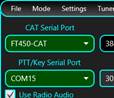
17 – Check this to enable the use of audio channels to the radio.
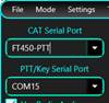
18 – Serial port to be used for PTT (used only if PTT not sent over CAT).
19 – Serial port to be used for CAT communications.
20 – Application main menu bar.
21 – Baud rate for the CAT serial port.
22 – Check here to route audio to/from a headset.
Once all relevant fields are set, click on the START button to enter Direct Control mode. See here how to operate in this mode. If you check AutoStart, the application will automatically enter Direct Control mode when next started.
Server mode
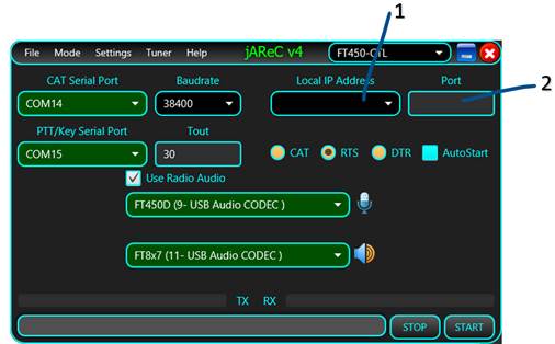
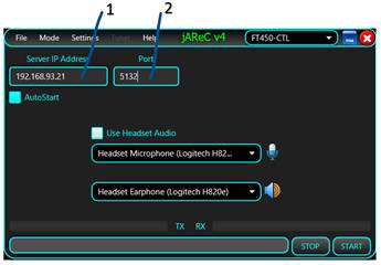
This is the screen displayed when Server mode has been selected as operational mode.
This is the program’s native mode, when connecting from a jAReC v4 client or PocketRxTx v4 (when available). The elements displayed in this interface that are the same as in the Direct Control mode have the same usage. These are the new elements.
1 – List of IP addresses available on the local system. This is just for information purposes (to know where to connect to from the client). The server will listen in any case on all available IP addresses of the PC. You don’t have to set this combo box to a specific value.
2 – The TCP port used to connect from the client this needs to coincide with the TCP port number defined in the client program. The same port number (but using UDP rather than TCP, protocol) will be used for the transfer of audio data between the server and the client programs.
Server mode (v3)
This mode is used only when the client is the PocketRxTx v3.x Android application. As soon as PocketRxTx v4 is available, this mode will be removed. The controls are the same as in the native server mode (above).
This is the screen displayed when Server mode(V3) has been selected as operational mode.
Client mode
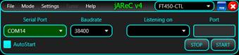
This is the screen displayed when Client mode has been selected as operational mode.
1 – Enter the IP address or the fully qualified domain name for the jAReC server that you want to connect to. (Tip: If testing by running a second copy of jAReC as the client on the same PC as is running jAReC in server mode – the “localhost” IP address of 127.0.0.1 can be entered here).
2 – Enter the TCP port (this must match the port number set in the server program).
This mode is used to remotely connect to a previously installed jAReC server instance.
The remaining fields have the same usage as in the Direct Control mode.
Bridge Mode
This is a simple bridge mode, between the network and a serial port and can be used for other purposes to make serial devices network accessible. As soon as the client connects, data is passed in both directions in a transparently.
Cfg Builder
The last option at the bottom of the Mode pull-down menu will launch the configuration builder utility. This is a graphical tool to help users create, edit and test radio configuration files to avoid the requirement of editing the file manually, so reducing the chances of corrupting a radio file. For more details about the configuration builder, check the dedicated chapter here.
Settings Menu
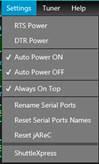
RTS Power, DTR Power – When checked, RTS and/or DTR signals in the CAT serial port are set high (1). This can be useful for some CAT interfaces that are powered from the serial port.
Auto Power ON, Auto Power OFF – When checked, the radio is automatically powered on and/or off when jAReC connects/disconnects from the radio. For this feature to work, a CAT command SET_POWER must be defined for the radio being used.
Rename Serial Ports – You can give friendly names (aliases) for the serial ports. To rename a serial port (CAT or PTT), click on this menu item. The serial ports background will change from Green to dark gray and you can edit the name.
Enter the desired name (minimum 4 letters) and then press ENTER. The new alias for the port will be visible with a green background.
NOTE: You can rename only one port at a time. To rename another port, click again on Rename Serial Ports and follow the same procedure.
Reset Serial Ports Names – Click on this menu item to return to the standard serial port naming.
Reset jAReC – This will remove the jAReC configuration file and all existing profile files. jAReC will restart with factory default settings.
ShuttleXpress – This menu item will be visible only in Direct Control and in Client modes and only if a ShuttleXpress device was connected to the PC before starting the application. Click on it to start ShuttleXpress configuration. A new form will be opened.
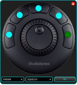
Click on the round dot assigned to the button you wish to configure, or directly on the corresponding button from the ShuttleXpress. The selected button dot will become green. You will be able to select any available parameter for the radio, or one of the following commands: CONNECT, MUTE, PTT, PTTLCK or TUNE. Only five buttons are user configurable. By default, the buttons are programmed as follows: 1 – PTT, 2 – PTTLCK, 3 – CONNECT, 4 – TUNE, 5 – SQUELCH. Click SET when you have changed the buttons that you wished to change.
The central knob is used for fine tuning, or to adjust a parameter. If a button is assigned a parameter, click on the button to set the parameter, use the knob to adjust its value and then click again to return to the default function of the knob (frequency tuning). The crown is used for fast frequency tuning only (UP/DOWN). The tuning step is increased with the rotation angle (left for frequency down, right for frequency up).
When in Server, Server (v3) or Client mode, another menu item is available in the Settings section – Set Password.
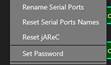
You will be prompted to enter the password you wish to use to securely connect between the client and server programs. The password is sent over the network and saved in the configuration file in an encrypted format.
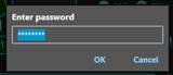
If the password was previously saved, it will be displayed as asterisks. When you enter a new password, the text is in the clear.
Tuner Menu
This is used to select what’s happen when you click on the TUNE button.

None – no tuner available, so TUNE button will do nothing
Transceiver – Internal transceiver ATU is used (or an external unit directly controlled by the radio). Clicking on the tune button will start the automatic antenna tuning process.
External – A manual external tuner is being used. Pressing on tune, the transceiver will be set to a predefined mode and power (usually CW/1W) and PTT will be activated. Click here to see how you can configure the mode and power to be used for tuning.
Help Menu
From here you can access this application user guide, some info about the current environment and links to different kind of information related to jAReC or other of my hardware and software projects.

Content – provides access to the multilingual online application user guide (in fact exactly the same as this document only in HTML format)
History – Will display the application history starting with the first v4 beta release.
Donate – Pressing this causes a direct PayPal link to appear. If you want to contribute to the further development and support of this application, please do so.
About – Displays some information about the OS, java and application version in use as well as the available audio interfaces.
Android – Get more information about the PocketRxTx Android companion App for jAReC, including download links.
jAReC Forum – Clicking this will access the jAReC v4 section of YO3GGX’s Forum. Please use this forum for any questions related to this application.
My Applications – Gives access to the web page with all my published applications.
My HW Projects – Gives access to the web page with documentation for all my published hardware projects.
Direct Control mode
After you configure the mode as described here, press the START button. The main radio control window will open.
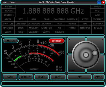
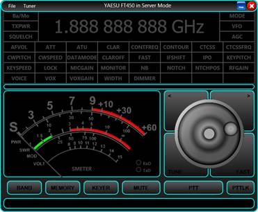
Click on the CONNECT button to connect to the radio. If the connection is successful, all the parameters defined in the radio models “radio” file will be read from the radio and the display adjusted accordingly. The example below is for a Yaesu FT450D.
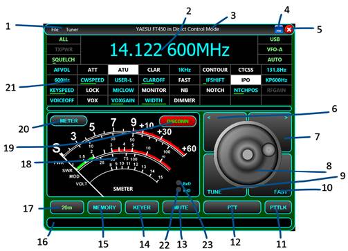
Controls - description:
1 – Radio window bar menu. From the File dropdown menu you can download or load a radio configuration file, open call logging, or exit this radio panel. To learn how to operate the Call Logging feature, click here.
The Tuner dropdown menu has the same functionality as the one described here.
2 – The frequency display. The frequency may be displayed in kHz, MHz or GHz. By clicking on the frequency display, the following form will pop-up:
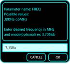
You may enter the desired frequency in MHz. You can optionally add the mode name on the end. For the mode name you can use just the first letter (l=lsb, u=usb, a=am, f=fm, c = cw). If special modes are defined in the radio config, add the full mode name (ex. user-l).3 – Here is where the radio brand, model and current app operation mode is displayed.
4 – Application window minimize button.
5 – Application window exit button.
6 – Step frequency down. The “Brute step” value is used, which is defined in the configuration file see here.
7 – Step frequency upwards. Again the “Brute step” value is used, which is defined in configuration file see here.
8 – Tuning knob. This is operated by using the scroll wheel on the mouse.
9 – TUNE button. See here how this button operates based on the selected antenna tuner mode.
10 – FAST button. When activated, tuning step is increased 10 times – i.e. the digit being adjusted is one position to the left of when operating in non-FAST mode (This applies to both when using the knob and the UP/DOWN buttons) and “FAST” is displayed in the top right corner of the frequency display.
11 – PTTLCK button. This is used to toggle PTT status. “click-on” / “click-off”.
12 – PTT button. Used to set the transceiver in Tx only when the button is pressed.
13 – MUTE button. This will toggle mute of the audio from the radio (if audio routing is being used).
14 – KEYER. Enter the Keyer panel. This feature allows you to send pre-typed CW. More details about this feature can be found here.
15 – MEMORY. Save current frequency, mode and other settings into, or recall from, one of the 16 available memories. More about working with memories here.
16 – Status message bar, used to display error or informative messages.
17 – BAND selection button. Pressing this brings up a selection panel to switch to bands supported by this radio.
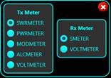
18 – Analog meter used to display one of the following values (see point 20 below): S, SWR, PWR, ALC, MOD, VOLT – if they are supported by this radio’s CAT command set.
19 – Button used to connect or disconnect from the radio via a serial, USB or Bluetooth port.
20 – Use this button to select what meter should display during Rx and Tx. Selection is done in the pop-up window shown below. If a specific meter is not defined in the radio configuration file, you will not be able to select it.
21 – Displayable and changeable Radio parameters. What appears here is defined in the radio configuration file. Position on the screen is determined by the sequence in the LSTLABELS parameter in the radio’s configuration file. The six parameters at the top (left and right side of the frequency display) are fixed positions and cannot be modified by the users through changing the configuration file. To indicate this , they are represented in light green on a black background. Up to 32 definable + the set 6 parameters can be displayed in the interface.
Parameters can have discrete or linear values. The display convention for the parameters with discrete values is as follows:
· If the parameter is off, parameter name is displayed with white text on a black background.
![]()
· If the parameter is on, parameter name is displayed with black text on a white background.
![]()
· If the parameter has a particular value, that value is displayed with turquoise characters on a black background.
![]()
Parameters with linear scale values are displayed with the parameter name in turquoise characters and a black background, plus a light green bar representing the value (from 0 to 100% of the available values).
![]()
You can hover the mouse over the parameter’s box to get more details and possible values for that parameter.

Click on the parameter to change the current value. There are 3 possible situations:
· Parameter with only two values (ON/OFF). The parameter value will be toggled and the new value displayed accordingly (see text under point 21 above)
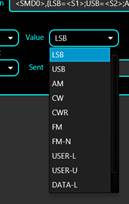
· Parameter with multiple discrete values. The following form will be displayed (e.g. for MODE):

Use the mouse scroll wheel, the “<” “>” buttons, or the ShuttleXpress central knob (if available) to set the desired value. When ready, click on the main label (MODE=LSB in the example above), or respective parameter button on the ShuttleXpress device to close the form.
· Parameter with linear scale values. The following form is displayed:

Use your mouse to adjust the slider to the desired value. Click on the MID button to set the parameter to the median value. This can be very useful if you have values that go from negative to positive (symmetrically). In that case you will set the parameter to 0.
22 – TxD virtual LED. This LED will flash when CAT data is sent to the radio
23 – RxD virtual LED. This LED will flash when CAT data is received from the radio
Working with memories
Click on MEMORY button in the radio panel to open the memories panel.
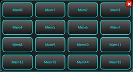
You can load up to 16 memory locations. In each memory location, all defined parameters are saved.
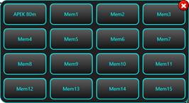
A long press on a memory button until the background goes green will store the current settings. You will then be prompted to enter a label for the memory location.

Click the Save button to save the settings to that memory location.
When you click again on the MEMORY button on the radio panel you will see the previously saved memory(s).
Click on a defined memory location to recall all saved settings into the radio.
Call Logging
When in Direct Control mode or in Client mode, by clicking on the File > Call Log menu item or simply pressing the “L” key on the keyboard you will enter the Call Logging applet. A new form will be displayed that is attached to the radio control form’s right hand side.
NOTE: The current jAReC version only supports ADIF (version 3.1.1.) as the call log file format.
NOTE: To use all the available download features, you must have a paid QRZ.com XML subscription. With a free QRZ.com account, you will be able to get only some basic info about a registered callsign (Name, QTH and Country).
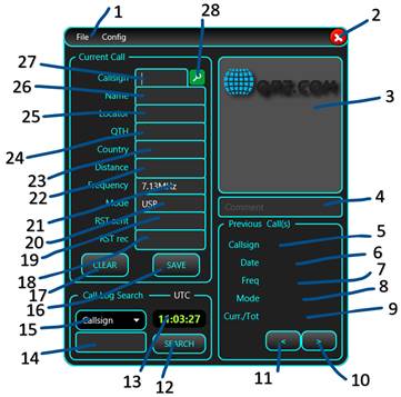
1 – Call Log Window menu bar, containing File and Config menu sections.
The File pull down Menu is used to create a new Call Log file (New), to open an existing Call Log file (Open) or to save currently loaded Call Log under a different filename. When you start Call Log for the first time, you are prompted to create a new Call Log file, or load an existing one (for search or edit/append purposes). The call log files are stored in the config folder under the folder where you installed jAReC.
Currently the application does not allow you to delete an existing Call Log record, so if you need this, you must edit the log file directly.

The Config menu is used to set your callsign and to enter your QRZ.com credentials. The credentials are only stored locally on your device, encrypted in the jAReC profile file.

Click on QRZ credentials. You will be prompted to enter credentials and your own Callsign.
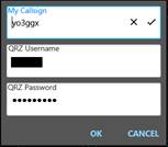
Click OK when ready. If the information you entered is valid, a message will be displayed in the main radio panel status bar, stating that your subscription is validated, when the subscription expires (or “non-subscriber” if you are using a free qrz.com account) and the number of queries you have performed.
![]()
Any QRZ query is performed using a session key, obtained based on your username and password when you start the application and enter Call Logging. If you leave the Call Log window open for a longer period (hours or days), the session key may expire. If at some point you no longer get data for a callsign that is defined at qrz.com, try to resolve this by clicking on Config > (Re)Get QRZ Key. A new key will be generated.
If your qrz.com credentials username or password is invalid, you will get an error message in the main radio panel status bar.
![]()
2 – Exit button. Is used to close Call Logging feature panel (this can also be done by selecting file/exit).
3 – When querying the QRZ database, and you have an XML subscription, the picture used on qrz.com for this station will be displayed here, if any is available.
4 – You can enter a comment for each call log record. This is optional.
Previous Call(s) section is used to display the results when you do a log search in your currently loaded file (see Call Log Search section below).
5, 6, 7, 8 – Previous log entry showing Callsign, Date, Frequency and Mode for the entered call sign in the search box.
9 – Number of search results / number of total calls in the search result list from the log file.
10, 11 – Used to go up/down in the call sign search result list.
12 – Click here to start the search in the currently loaded call log file. You must first select the parameter you want to search for (15) and then enter the text to search for (14).
13 – Here is displayed the UTC clock, that will be used for entering any new contact log record.
14 – Here you enter the text you are searching for in the currently loaded log file. This can be a substring of the field value.
15 – Select from the dropdown list in which field of the call record you want to search, matching against the text in (14). You can choose between: Callsign, Country, Band, Continent, CQ zone, DXCC, ITU zone, and IOTA reference.
Current Call section. Here is where you enter the data for a new contact. If you have a valid paid QRZ.com XML subscription, you only need to enter the callsign of your correspondent and then press ENTER or click on the search button (28). All the other fields will be automatically filled in, except RST sent (19) and RST rec (18). (if using a free qrz.com account, the Name, QTH and Country fields will be completed).
16 – SAVE button. In order to save a call record in the log, the following fields are mandatory: Callsign (27), Frequency(21), Mode (20), RST sent (19) and RST rec(eived) (18). Frequency and Mode are automatically filled in for you from the radio panel. If the QRZ query is successful (callsign registered in QRZ.com), you only must fill RST sent (19) and RST rec(eived) (18) fields and then to press SAVE button. Call starts and end time and date are automatically set based on the current UTC values at the time of log entry.
17 – CLEAR button. If you don’t want to save the current contact to the log, click on CLEAR to clear all the call information from the form. All fields will be cleared out except Frequency and Mode, that are automatically updated from the radio panel.
18, 19 – RST rec (the RST you received from the other ham) and RST sent (the one you gave to the other ham for the current contact).
20 – MODE field for the current call. This is automatically filled from the radio panel but can be overwritten.
21 – FREQUENCY field for the current call (in MHz). This is automatically filled from the radio panel but can be overwritten.
22 – The distance between your station (if you have a valid record in QRZ.com and an XML subscription account) and the station of your contact. This is automatically calculated based on Locator (25) field, cannot be overwritten by the user and is displayed in both miles and kilometers. This is how it looks (no real data used in this example).
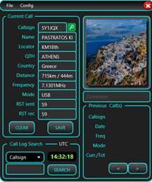
23 – Contacts’ Country – automatically returned from a QRZ query, but you can edit this field
24 – Contacts’ City or County (QTH) – automatically returned from a QRZ query, but you can edit this field.
25 – Contact’s Maidenhead Grid Square Locator – automatically returned from a QRZ query (only with an XML qrz.com (paid) account), but you can edit this field.
26 – Contact’s operator name – automatically returned from a QRZ query (only with an XML qrz.com (paid) account), but you can edit this field.
27 – Contacts’ call sign. You must enter this field manually, for each call. (Press enter after entering this to initiate the qrz.com lookup).
28 – Click on this button (or press ENTER) after you enter the callsign to start querying the QRZ database.
If you have a paid QRZ XML subscription, you can click on the station picture to get more information about the station. A new form will be opened. The fields are the standard ones from a call log entry. MQSL (Manager QSL), EQSL, or LOTW labels are displayed with green background if that specific method to receive QSLs is accepted, red if not.
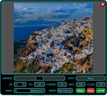
If you click on the picture from this panel, the station’s web page will be displayed (if defined in the QRZ database). If not, the standard QRZ web page for the station will be displayed.
You can search through the current log for specific records (see 12, 14 and 15). Let’s try for example, to search for all contacts with Germany. Select Country as field and enter Germany as search text, then click on SEARCH button.
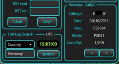
In the example above, there are 219 logged contacts with stations from Germany. Callsign, date, frequency and mode are directly displayed. Use “<” and “>” buttons to browse through the results list. Click on the callsign (from Previous Call(s) section) to query QRZ database about that callsign.
KEYER
Click on the KEYER button when in the radio panel to enter the CW keyer. The following panel will be displayed.
As soon as you enter the Keyer, the radio will be automatically set to CW mode.
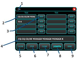
1 – Keyer window menu bar. Use File > Save to save current macros definition after you enter or edit them.
2 – pre-set text sequences. You can define up to 8 text macros to be used with a simple click.
3 –ADD button to add the chosen macro text to the box containing the text to be transmitted (4).
4 – Box containing the text to be transmitted. You can enter/edit the text using the keyboard and/or add predefined text from one of the 8 locations (2).
5 – Button used to close the Keyer panel.
6 –STOP button to immediately stop an in-progress transmission.
7 –CLEAR button to clear the contents of the transmitted text box (4).
8 –Transmission speed (in words per minute). This setting corresponds to the setting in the radio’s configuration file and is user adjustable.
9 –SEND button to send the text from (4) in CW. PTT and CW KEY interface settings are explained here.
When you click on the CLOSE (white X on red background) button the Keyer panel is closed, and the radio is set back to the mode it was in before the Keyer panel was activated.
Server mode
In this mode, your computer will act as a server for the transceiver, allowing another instance of jAReC in Client mode (or the PocketRxTx v4 Android application, which is not yet available) to connect over the network (LAN or Internet) and control the radio. To configure this mode, check here. When ready, click on START. You can set jAReC to automatically start this mode when application run by setting AutoStart.
Standard radio panel will be displayed, but without any usual configuration options.
jAReC in this picture is waiting for a connection from a jAReC (or PocketRxTx v4) client. The radio panel of the server and the client program will be kept continuously in sync. As soon as the connection is successfully established, the server panel will have the same appearance as in Direct Control Mode, but without local control. The background will go dark green when the client is connected dark red when radio is in Tx mode.
Server mode (v3)
This is a server mode used only for connections from the PocketRxTx v3 Android application. Check here to see how to configure this mode. It is backward compatible and fully replaces the jAReC v3 application, which is now obsolete. When you click on the START button, the panel’s background goes dark yellow and is waiting for a connection.
When the client connects, the panel’s background goes dark green and when the radio is in Tx, the background changes to dark red.
Client mode
This mode is used to connect to your radio over the network, through another jAReC instance in server mode. For details about how to configure this mode, check here. When clicking on the START button, the same radio panel as in Direct Control mode will be opened. You then can operate the Client mode in the same way as Direct Control mode, as described here.
NOTE: Settings menu (describe here) must be pre-configured in the server panel, it is unavailable on the client.
Bridge mode
Just click on START to enter transparent bridge mode, no other configuration required.
Cfg Builder
Configuration Builder is an integrated graphic tool used to build/edit/test radio configuration files. If you are not very familiar with the syntax used for the configuration files (described here), it is recommended to use this tool instead of directly editing the files.
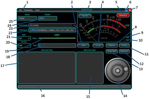
Before entering Cfg Builder, you must configure the connection to the radio in Direct Control mode, as described here. As soon as you click on Mode > Cfg Builder in the main application screen, the following panel is displayed.
NOTE: If you enter Cfg Builder before downloading or opening a radio configuration file, all fields will be empty.
1 – Configuration Builder menu bar. File menu
For File>Download … and File>Open … options please refer to the documentation here.
File>Save Radio Config File is used to save the configuration file after you edit it. When saving the file, this is rebuilt with all definitions in alphabetical order, so even if you edit the file manually, at the end is a good idea to load it into the Cfg Builder and then save it, to keep it in an ordered format.
File>CAT Protocol is used to access the web page containing the CAT protocol documentation for the current radio. This URL link is defined in the configuration file.
Click on File>Exit to exit Cfg Builder.
Parameters
> Other menu. This is used to define extra parameters for the radio.
The following form will be opened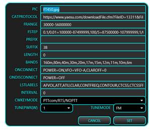
For more details about each parameter, check the radio configuration file description here.
Tuner menu. Please refer to description here.
2 – SEND button to send currently selected/created CAT command to the radio to test it.
3 – METER button selects what is displayed on the meter (for Rx or Tx). More details here.
4 – CLEAR button used to clear the content of the Returned data and Returned value fields.
5 – CONNECT button connects to the radio. When connected, the panel background will go dark green, and the meter will light up.
6 – Click this button to minimize the Cfg Builder window.
7 – Click this button to close Cfg Builder.
8 – REMOVE button removes the currently selected command from the configuration file.
9 – Virtual Rx LED, which flashes when data is received from the radio.
10 – Virtual Tx LED, which flashes when data is transmitted to the radio.
11 – STORE button - used to store current command after you add it or have edited it.
12 – READ_ALL button reads from the radio all parameters which have a defined READ command. The result is displayed in the Returned data and Returned value fields.
13 – READ-ONE reads from the radio the value of the currently selected parameter (even if SET, PAT or CAL type are selected).
14 – Frequency tuning knob, used to test fine tuning commands.
15 – If the received raw data from the radio contains a valid defined parameter value, it is interpreted and displayed in this field. If the received data is not valid, but it is for a valid parameter, ‘parname=?’ is displayed. If the parameter cannot be determined from the received data, ‘?=?’ is displayed here.
16 – Status bar - used to display informational or error messages during Cfg Builder operation.
17 – Raw data as received from the radio is displayed in this field in the selected format as defined in the pull-down options under (20).
18 – Once the command is built from a definition, what will be sent to the radio is displayed here in RAW format.
19 – If the parameter has an analog value, a slider is used to set the parameter value. If the parameter has discrete values, a combo box is used to set the desired value.
20 – This combo box selects the format to be used for the Sent and Returned data fields. Some radios use a string based (STR) protocol (including Yaesu FT450, 991, etc. & Kenwood), or a byte based (HEX) protocol (Yaesu FT8x7, most if not all, ICOMs). For some radios (like FT8x7) you may also need a binary representation (BIN), as some parameters are assigned to specific bits.
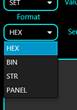
The last option in this dropdown is PANEL, with a usage similar to in the Direct Control mode. This can be used to see how parameters are assigned to different positions on the screen and check the various parameters controlled through the interface.
21 – This combo box is used to select the parameter definition section: SET (for the SET commands), READ (for the read commands), PAT (for the radio’s layout or pattern of returned data) or CAL (for calibration data, used with the meter displays).
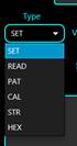
22 –This is the definition (pattern) of the current command, using the standard syntax. Check your radio configuration file format here for more details.
23 – Combo box containing the list of already defined commands.
NOTE: For each parameter, all 3 definitions must exist (SET, READ and PAT), even if for some parameters, READ and PAT are empty (no read command available, only SET command).
24 – The radio model is displayed here.
25 – The radio Brand is displayed here.
Connecting to the radio
When you connect to the radio from the Cfg Builder all defined parameters are automatically read from the radio. The two lists (data and value) are kept in sync. If you click on any item from one of the lists, the corresponding item from the other list is selected too.
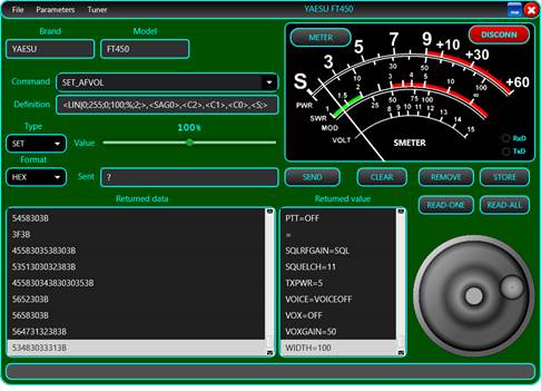
You can scroll through the Returned data and Returned value lists to check in case for a parameter there is a value returned that cannot be decoded.
NOTE: In the example above, the returned data ‘3F3B’ (second line down) is a Yaesu “command not ok” message for one of the commands sent. There are some situations in which requested parameters cannot be read. In this particular case, the RFGAIN parameter cannot be read because the radio is set to use SQUELCH at the moment instead of RFGAIN (SQLRFGAIN=SQL). As jAReC continuously polls the radio during normal operation so that the parameters will be always kept synchronized between the radio and jAReC.
Creating a new command
To create a new command, select New from the end of the list of already defined commands (23). Type the command name in (23) and then write its definition in (22). When ready, click on STORE (11). To test the command, set the desired value for the parameter in (19) and click on SEND (2).
NOTE: If the Sent (18) field displays ‘?’, then the command definition is wrong, and the application is not able to build it. Do not click on SEND again if the definition is wrong. You must check the syntax again and correct it first.
Editing an existing command
To edit an existing command, select it from the list of already defined commands (23). Edit the command definition in (22). When ready, click on STORE (11). To test the command, set the desired value for the parameter in (19) and click on SEND (2).
NOTE: If the Sent (18) field displays ‘?’, then the command definition is wrong and the application is not able to build it. Do not click on SEND again if the definition is wrong. You must check the syntax again and correct it.
Displaying data received from the radio
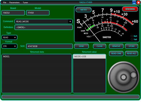
Depending on the protocol used by the radio, select the correct data format in (20). For each SET command, the radio returns a confirmation message or an error indication. Currently this data is not used in normal operation but can help you debug your changes and additions to the configuration file. When you send a READ command, the radio returns the parameter value in a format specified in the CAT protocol in the Returned data field.
This is an example of data returned by a Yaesu FT450 for a READ_MODE command, in STR (string) format mode.
Some commands may return multiple answers. In the following example, reading the mode value (CW) will return the currently selected filter value (FLT1) too (ICOM IC7300).
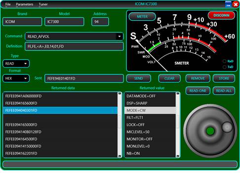
Radio configuration file
The radio configuration file contains several sections that will be described below. jAReC can support 3 main radio protocol categories:
· String based protocol - variable length, both prefix and suffix used for both sent and received data. (Yaesu FT450, FT950, FT991, Kenwood, etc.)
· Variable length hex-based protocol – byte-based data, both prefix and suffix used for both sent and received data. (ICOM radios)
· Fixed length hex-based protocol – byte-based data, no prefix and no suffix used. (Yaesu FT8x7 radios)
General section
Here you define specific parameters for the radio. This sample is from a Yaesu FT450 config file. Some parameters are self-explanatory. Most of the parameters are commented inside the configuration file.
; **** Generic section ****
TIMESTAMP=10/16/2021|12:45:07 <- this timestamp is generated when you save the config file from Cfg Builder.
VERSION=4 <- configuration version (not compatible with v3)
BRAND=YAESU
MODEL=FT450
PIC=FT450.jpg
SIGRADIOS=$1gG49@A10XsG
; Location for the CAT protocol documentation (HTML or PDF file)
CATPROTOCOL=https://www.yaesu.com/downloadFile.cfm?FileID=13311&FileCatID=158&FileName=FT-450D_CAT_OM_FENG_1710-B.pdf
; Radio Address (used only for iCOM radios)
; Hexa format (2 chars)
RADIOADDRESS= <- for IC7300 is RADIOADDRESS=94
; Frequency coverage, in Hz, sections separated by ','
; format: FRANGE=f1-f2,f3-f4,f5-f6,...
FRANGE=30000-56000000 <- for IC7300 is FRANGE=30000-60000000,65000000-74800000
; Frequency step per frequency range, in KHz, freq range in Hz
; format: FSTEP=<brute_step1>/<fine_step1>=<freq_interval1_min>-<freq_interval1_max>,<brute_step2>/<fine_step2>=<freq_interval2_min>-<freq_interval2_max>, ...
; brute for +/-, fine for knob tuning
FSTEP=0.1/0.01=100000-87499999,100/5=87500000-107999999,1/0.01=108000000-136999999,25/0.01=137000000-137995000,6.25/0.01=138000000-173999999,25/0.01=174000000-215999999,12.5/0.01=216000000-224999999,12.5/0.01=225000000-469999999,25/0.01=470000000-1300000000
; CAT command / radio answer prefix (in standard command format), empty string if none
PREFIX= <- for IC7300 is PREFIX=FEFE
; CAT command / radio answer suffix (in standard command format), empty string if none
SUFFIX=3B <- this is ‘;’ char, for IC7300 is SUFFIX=FD
; Command / radio answer length (in bytes), if fixed length, 0 if variable length
LENGTH=0 <- for FT817 is LENGTH=5
; Interval (in ms) between successive commands sent to the radio. Usual is 0, but with some radios a bigger delay may be required to prevent overlapping answers.
INTERVAL=0 <- most of the radios will use 0 for this parameter
; Serial Interface, pin used and mode (PTT must be on or off during keying) for CW keying .
; 0=PTTcom/DTR/NOPTT
; 1=PTTcom/RTS/NOPTT
; 2=CATcom/DTR/NOPTT
; 3=CATcom/RTS/NOPTT
; 4=PTTcom/DTR/PTT
; 5=PTTcom/RTS/PTT
; 6=CATcom/DTR/PTT
; 7=CATcom/RTS/PTT
CWKEY=1 <- this mean RTS line over PTT serial port is used for
Keying, PTT not required to be activated before keying.
; List of available Bands
BANDS=160m,80m,40m,30m,20m,17m,15m,12m,11m,10m,6m
; Parameters(s) to be set when connected/disconnected to/from the radio (ex. commands to control external devices, PSUs, antennas, etc.)
; format param1=value1,param2=value2,...
; you can add as a command a pause in the standard format PAUSE=xxxx
; 'paramx' can be any of the radio parameters (including script names)
; if POWER=ON is used, then this must be in the first position
; example:
; ONCONNECT=FREQ=3705000,MODE=LSB,<P1000>,AFVOL=50
ONCONNECT=POWER=ON,VFO=VFO-A,CLAROFF=0
ONDISCONNECT=POWER=OFF
; List of all SET/READ/PAT/CAL parameters - you must define each parameter in each of the three groups with exactly the same name, even if empty
; except METERS (S,SWR,PWR,ALC,MOD,VOLT) for which SET commands are not defined
LSTPARAMS=ACK*,AFVOL,AGC,ALCMETER,ATT,ATU,BAND-A,BAND-B,BEACON,CLAR,CLAROFF,CONTFREQ,CONTOUR,CTCSS,CTCSSFRQ,CWPITCH,CWSPEED,DATADISP,DATAMODE,DIMLVL,DIMMER,FAST,FREQ,IFSHIFT,IPO,KEYPITCH,KEYSPEED,LOCK,METERSEL,MICGAIN,MODE,MODMETER,MONITOR,NACK*,NB,NOTCH,NOTEPAD,NR,NRLEVEL,NTCHPOS,POWER,PTT,PWRMETER,RFGAIN,SMETER,SQLRFGAIN,SQUELCH,SWRMETER,TXPWR,VFO,VFOEQ,VOICE,VOX,VOXGAIN,WIDTH
Commands definition syntax (TAGs)
Each command has the following format: cmdtype_cmdname=byte1,byte2,... where cmdtype can be SET,READ,PAT(pattern) or CAL(calibration).
NOTE: For a specific parameter/setting, cmdname must be identical for SET, READ, PAT and CAL !!!
List of available TAGs:
Bytes represented as hex values
xx,xx,... - bytes represented as hex values, separated by commas (x represents a hex char, ‘0’ to ‘F’).
Bytes represented as binary values
{10010110} - a binary represented byte
Radio address
<A> - replaced with radio address as one byte
A string
<Sabcdef> - string 'abcdef' (one byte generated per char)
A char digit
<Cx> - 'x' order digit, from 0 to F (15) - frequency up to 1000THz supported, one byte
Two digits packed in a byte (BinaryCodedDecimal)
<Dxy> - 'x' and 'y' digit order - 2 BCD packed digits in the same byte, from F(1000THz) To 0(Hz)
Delay (pause) between 2 bytes
<Pxyzu> - add a 'xyzu' ms delay between 2 consecutive bytes
Bytes based on parameter value
{name1=hex1;name2=hex2; ...} - For each named parameter value (name1, name2, etc.), set the byte with the corresponding hexadecimal value (hex1, hex2, etc.).
Example (FT450):
{OFF=<S0>;FAST=<S1>;SLOW=<S3>;AUTO=<S6>;}
If the value is OFF, the byte is the ASCII code of ‘0’ char, if the value is FAST, the byte is the ASCII code of ‘1’ char, etc.
You can have SET commands affected by other parameters. For example, SET_MODE for IC7300 radios is dependant on FILT parameter as well. Then add this as a suffix for the byte of the parameter name followed by ‘:’.
SET_MODE=FE,FE,<A>,E0,06,{MODE:LSB=00;USB=01;AM=02;CW=03;RTTY=04;FM=05;CWR=07;RTR=08;},{FILT:FLT1=01;FLT2=02;FLT3=03;},FD
This is another example for FT450. The format of the SET_FREQ command depends upon the currently selected VFO.
SET_FREQ=<SF>,<VFO:A='A';B='B';>,<C7>,<C6>,<C5>,<C4>,<C3>,<C2>,<C1>,<C0>,<S;>
Linear parameters represented as one or multiple bytes
<LIN|val0;val1;val2;val3;M;stp;>
Where:
· val0 = min value to be sent to the radio
· val1 = maximum value to be sent to the radio
· val2 = minimum parameter value
· val3 = maximum parameter value
· M = measuring unit (W,Hz,%,etc.)
· stp=change step
Example for Tx power from 1 to 100W, but value to be sent is between 0 and 255: SET_TXPWR=<LIN|5;100;5;100;W;1;>,<SEX048>,<C2>,<C1>,<C0>,<S;>
Custom scripts
Custom commands (scripts to be executed on the operating system where jAReC is running) are defined like any other CAT command, using the following format:
SET_SCRIPTNAME=[full_path_to_the_executable_name and parameters, if any]
Replace '\' with '\\' in the file path for Windows systems
Include command in ' " ' if contains spaces
Example to start Notepad:
SET_JAVAVER=["C:\\Windows\\notepad.exe"]
Returned value (if any) will be displayed as message box.
Writing data to EEPROM locations (Yaesu FT8x7)
<WEaddr;xxxxxx11;xxxxxxxx;>
Where:
· addr is the EEPROM address to write to (2 bytes). 2 consecutive EEPROM locations are written with a single SET command.
· ‘x’ - the bits that must remain unchanged.
· ‘1’ - the bits that depends on the parameter value.
Example:
SET_AGC=<WE0057;xxxxxx11;xxxxxxxx;>,{AUTO=00;FAST=01;SLOW=10;OFF=11;}
Reading data from an EEPROM location (Yaesu FT8x7)
<REaddr>
Where:
· addr is the EEPROM address to write to (2 bytes). 2 consecutive EEPROM locations are read with a single READ command.
Example:
READ_AGC=<RE0057>
Multiple definitions for the same parameter
You can add multiple definitions for a specific parameter (ex. ICOM patterns for MODE, FREQ). Keep the same parameter name and add one or more '*' at the end of the parameter name. One example where this is needed is when the data received back from the radio could be one or two bytes long e.g. 10 or 255.
Patterns definition syntax (TAGs)
Pattern definitions are similar to the corresponding SET command.
Simple analog value packed as a string (same as for the associated SET command)
PAT_AFVOL=<SAG0>,<C2>,<C1>,<C0>,<S;>
Simple analog value packed as two bytes
PAT_AFVOL=FE,FE,E0,<A>,14,01,<D32>,<D10>,FD
Simple discrete values parameter received as a string
PAT_AGC=<SGT0>,{<S0>=OFF;<S1>=FAST;<S3>=SLOW;<S6>=AUTO;},<S;>
Multiple parameter values received in a single string
PAT_FREQ=<SF>,{VFO:<SA>=VFO-A;<SB>=VFO-B;},{FREQ:<C7><C6><C5><C4><C3><C2><C1><C0>;},<S;>
Multiple parameter value possibilities received in a byte based answer
PAT_FILT=FE,FE,XX,<A>,04,{MODE:00=LSB;01=USB;02=AM;03=CW;04=RTTY;05=FM;07=CWR;08=RTR;},{FILT:01=FLT1;02=FLT2;03=FLT3;},FD
Binary packed parameters value (in 2 bytes)
For an EEPROM read command, two bytes are always returned from two consecutive EEPROM addresses.
Example:
<B;5x43x211;87xxxx66;1:AGC;2:DISPLAY;3:PBT;4:NB;5:FST;6:METERSEL;7:VMETER;8:VOX;>
<B; - a binary byte definition
Here in the two bytes, we represent the bits that contain parameters value with digits and use ‘x’ for bits that can be discarded.
The number received in a bit can be further described, in text, in the pattern statement.
A parameter value can occupy one or more bit.
Multiple parameter values and formats in the data received from the radio after a read command is issued
Example: Reading frequency and mode with a single command
{FREQ:<D87><D65><D43><D21>;} - 4 bytes
{MODE:00=LSB;01=USB;02=CW;03=CWR;04=AM;08=FM;0A=DIG;0C=PKT;} - 1 byte
A byte that can be discarded
<XX> - This byte can be of any value, is not used for received data decoding.
Set command section
Here are some sample ‘set’ commands for different radios, to help you better understand how can you set different parameters using the syntax defined here.
Yaesu FT450
Set AF volume
SET_AFVOL=<LIN|0;255;0;100;%;2;>,<SAG0>,<C2>,<C1>,<C0>,<S;>
Set AGC
SET_AGC=<SGT0>,{OFF=<S0>;FAST=<S1>;SLOW=<S3>;AUTO=<S6>;},<S;>
Set Frequency
SET_FREQ=<SF>,{VFO:VFO-A=<SA>;VFO-B=<SB>;},{FREQ:<C7><C6><C5><C4><C3><C2><C1><C0>;},<S;>
Set Clarifier Offset (RIT)
SET_CLAROFF=<LIN|-9999;+9999;-9999;+9999;Hz;10;>,<SRC;R>,{+=<SU>;-=<SD>;},<C3>,<C2>,<C1>,<C0>,<S;>
Set IF Shift
SET_IFSHIFT=<LIN|-1000;1000;-1000;1000;Hz;10;>,<SIS0>,{+=<S+>;-=<S->;},<C3>,<C2>,<C1>,<C0>,<S;>
Set Power
SET_POWER=<SPS>,{OFF=<S0>;ON=<S1>;},<S;>,<P100>,<SPS>,{OFF=<S0>;ON=<S1>;},<S;>,<P500>,<SPS>,{OFF=<S0>;ON=<S1>;},<S;>,<P1000>
ICOM IC7300
Set AF volume
SET_AFVOL=<LIN|0;255;0;100;%;2;>,FE,FE,<A>,E0,14,01,<D32>,<D10>,FD
Set AGC
SET_AGC=FE,FE,<A>,E0,16,12,{AGC-F=01;AGC-M=02;AGC-S=03;},FD
Set Frequency
SET_FREQ=FE,FE,<A>,E0,05,<D10>,<D32>,<D54>,<D76>,<D98>,FD
Set RIT frequency
SET_RITFREQ=<LIN|-9999;+9999;-9999;+9999;Hz;10;>,FE,FE,<A>,E0,21,00,<D10>,<D32>,{+=00;-=01;},FD
Set Filter
SET_FILT=FE,FE,<A>,E0,06,{MODE:LSB=00;USB=01;AM=02;CW=03;RTTY=04;FM=05;CWR=07;RTR=08;},{FILT:FLT1=01;FLT2=02;FLT3=03;},FD
Yaesu FT817
Set AGC
SET_AGC=<WE0057;xxxxxx11;xxxxxxxx;>,{AUTO=00;FAST=01;SLOW=10;OFF=11;}
Set Frequency
SET_FREQ=<D87>,<D65>,<D43>,<D21>,01
Set Band A
SET_BAND-A=<WE0059;xxxx1111;xxxxxxxx;>,{160m=0000;80m=0001;40m=0010;30m=0011;20m=0100;17m=0101;15m=0110;12m=0111;10m=1000;6m=1001;FM=1010;AIR=1011;2m=1100;70cm=1101;PHANTOM=1110;}
Set Clarifier Frequency
SET_CLARFREQ=<LIN|-9999;+9999;-9999;+9999;Hz;10;>,{-=01;+=00;},00,<D32>,<D10>,F5
Read commands section
Read commands are very simple, and require no additional parameters, using the syntax defined here.
Some examples for clarification:
Yeasu FT450
READ_CWSPEED=<SEX021;>
ICOM IC7300
READ_AGC=FE,FE,<A>,E0,16,12,FD
Yaesu FT817
READ_AGC=<RE0057>
READ_FREQ=00,00,00,00,03
Patterns definition
Some examples for the 3 main protocol types.
Yaesu FT450
AF volume – simple linear value
PAT_AFVOL=<SAG0>,<C2>,<C1>,<C0>,<S;>
AGC mode – discrete parameter values
PAT_AGC=<SGT0>,{<S0>=OFF;<S1>=FAST;<S3>=SLOW;<S6>=AUTO;},<S;>
IF Shift – analog value with sign
PAT_IFSHIFT=<SIS0>,{<S+>=+;<S->=-;},<C3>,<C2>,<C1>,<C0>,<S;>
ICOM IC7300
RIT Frequency – analog value with sign
PAT_RITFREQ=FE,FE,E0,<A>,21,00,<D10>,<D32>,{00=+;01=-;},FD
AGC mode – discrete parameter values
PAT_AGC=FE,FE,E0,<A>,16,12,{00=OFF;01=AGC-F;02=AGC-M;03=AGC-S;},FD
AF volume - analog simple value
PAT_AFVOL=FE,FE,E0,<A>,14,01,<D32>,<D10>,FD
Yaesu FT817
This is the most complex format for a pattern. Multiple parameters values can be received in a single byte, so a binary pattern is used.
AGC pattern
PAT_AGC=<B;5x43x211;87xxxx66;1:AGC;2:DISPLAY;3:PBT;4:NB;5:FST;6:METERSEL;7:VMETER;8:VOX;>,{AGC:00=AUTO;01=FAST;10=SLOW;11=OFF;},{DISPLAY:0=OFF;1=ON;},{PBT:0=OFF;1=ON;},{NB:0=OFF;1=ON;},{FST:0=OFF;1=ON;},{METERSEL:00=PWR;01=ALC;10=SWR;11=MOD;},{VMETER:0=OFF;1=ON;},{VOX:0=OFF;1=ON;}
Calibration definition
For each meter you must define calibration data based on returned data from the radio after a READ command. If the returned value represents the final data, then the respective meter calibration data is empty. Calibration is done using a limited number of calibration points. The rest of the values are interpolated by the application.
The format for the calibration data for each calibration point is:
returned_data=real_data;
A special situation exists for the S-METER, where the values between S1 and S9 are represented as 100, 200, … 900. Values over S9 (+10dB .. +60dB) are represented as 910, 920, …, 960.
The following calibration definitions must exist in each config (even if some are not used for a specific radio):
CAL_ALCMETER
CAL_MODMETER
CAL_PWRMETER
CAL_SMETER
CAL_SWRMETER
This is an example (for the Yaesu FT450):
CAL_ALCMETER=0=0;120=100;
CAL_MODMETER=
CAL_PWRMETER=0=0;74=10;107=20;132=30;148=40;164=50;181=60;197=70;206=80;222=90;245=100;
CAL_SMETER=0=0;16=100;41=200;58=300;74=400;90=500;107=600;118=700;137=800;156=900;173=910;189=920;206=930;222=940;238=950;255=960;
CAL_SWRMETER=0=1;66=2;120=3;200=10;
Parameter labels definition
Only the parameters that are presented in the LSTLABELS definition are displayed in the interface. There are 6 exceptions, for the parameters that are assigned to a fixed position in the interface and cannot be removed (3 on the left-hand side of the frequency display and 3 on the right hand side. To ‘mark’ these parameters as non-removable, they are displayed in yellow:
· Preferred mode for the current frequency (part of the band – e.g. low CW, high SSB)
· TX power
· Squelch
· Mode
· VFO
· AGC
For all other display in the UI parameters, you can set the order (from left to right and then wraps to a new line) by the sequence that you list them in the LSTLABELS definition in the configuration file.
Program history (v4 only)
v4.0 – first public release (Dec 27, 2021)
jAReC_v4.0_user_guide_rev2.pdf Bucharest, Dec 29, 2021 – © Dan Toma – YO3GGX – yo3ggx@gmail.com