User manual
Contents
Program graphical interface design
Minimizing application and icon modes
* * * * * * * * * * * * * * * * * * * * * * * * * * * * * * * * * * * * * * * *
Overview
This application is based on several included plugins which can be enabled or disabled independently: infrared, X10, Bluetooth, Application, IR Dimmer, Winamp. You must define a minimum of one input and one output plugin in order to be able to operate in monitoring mode.
The application can be very useful for different applications:
- use an Ericsson Bluetooth enabled phone as a remote control for all your Home Automation devices. You will get the status on the phone display. You can command up to 10 different devices using a single phone;
- use an Ericsson Bluetooth enabled phone as a bi-directional Winamp remote control;
- monitor infrared and Bluetooth events and trigger any available output event;
- use an Ericsson Bluetooth enabled phone for presence detection;
- use an Ericsson Bluetooth enabled phone to control a PC application, through mouse events (ex. Powerpoint);
- analyze the sequence generated by a specific infrared remote control command (in a easy to understand graphical form);
- extract the data bits from the sequence;
- store the commands in the remote configuration file, automatically;
- import/export device configuration files;
- transmit the command using the PC for any 35-40KHz operated infrared remote control;
- generate new commands not available on the standard device remote control;
- transmit and receive infrared commands to/from specific zones only, using Frank's FirM interface;
- transmit commands to other remote controlled equipments (trough radio frequency, power line, etc.), using specific hardware interface;
- transmit basic X10 commands using a CM11/CM12 interface and friendly names (instead of X10 addresses), using the same COM port as for the infrared;
- reset a CM11/CM12 X10 interface when in "Power failure" status;
- generate specific infrared commands to drive the Univex Touch/Infrared Wall Light Dimmer for both ON/OFF and DIM/BRI;
- transmit application start/stop type commands (with or without desktop interaction) or even play sound files (WAV and MP3) as separate commands;
- transmit Winamp output commands, including OPEN and CLOSE (and automatically start Winamp when a valid command selected);
- monitor input for infrared commands and trigger any type of output commands as defined;
- use any WEB or WAP browser from anywhere in the world to control your home equipment (using infrared, X10, or any other available output plugin). You can include the CGI script in your own web pages, using any available Windows Web server (including IIS), with HTTPS support (then you can highly secure your web based connection to home web page).
<home>
The hardware interface
This application is fully compatible with the following serial interfaces:
- LIRC/WINLIRC (Standard DCD)
- IRMouse (inversed DCD) known too as Packard Bell Fast Media PC Infrared Remote
- IRMan (PIC based - allways a 48bit command, independent of the protocol used) - just to receive and learn commands in this version - then use it in the AutoM8it framework for input purpose only.
- FirM is basically a Standard DCD type Rec interface, including a DTR based send interface and support for infrared zoning.
- Bluetooth Serial Connection with an Ericsson phone (it can use IrDA too if there is a virtual COM port associated with infrared)
The DCD bit is used for the received signal and DTR or TxD for the send signal. The 36-40KHz carrier must be hardware generated for DTR based interface and it is software generated for TxD based interface.
Starting with the version 1.3.x, the IRMouse interface can be used to receive commands.
Two type of interfaces can be used to send commands (DTR based and TXD based).
One example for a full record/send interface is presented in the following picture. This is the one used by me to develop this application and is the best option for the advanced users.
It allows you to use the same COM port for both infrared and X10 interface (CM11/CM12).
Using R10 tune the oscillator frequency to a value between 35-39KHz.
In the left side of the connector is the receiver part, which is common for every type of transmitter you choose. It is based on an integrated IR receiver, like TSOP1738 or similar. It is powered from the same stabilizer as for the transmitter part.
More examples can be found on the LIRC/WINLIRC sites.
Now a very simple TX interface which can be build in a couple of minutes, directly in the DB9 connector case:
Two versions are presented, one very simple but with a range of only 1-2m and the other one with a greater range. You don't need any external power supply.
Simple send interface powered directly from TxD signal.
TxD based interface powered from the RTS line.
A much powerful interface can be found here. Just replace DTR input by TxD an this is it. There is no need to use another serial interface pin to power the send device.
The following schematic is from the IRMouse interface, which can be used to receive IR commands.
This is a very popular interface, available at a very low price on the net (around $10 on EBAY).
More information about it at: http://cgi.ebay.com/ws/eBayISAPI.dll?ViewItem&item=1773236093 or on the support site at: http://ebay.dennisbrenner.com/support/fastmedia.htm .
If you need a cheap and reliable interface just to receive and/or learn infrared commands then the following one is the best in price/performance ratio. You can build it for less than $5, inside a DB9-female connector case.
<home>
Program installation
To install the application just unzip the file irm.zip and run irm.exe.
If you have a previous version installed, do not forget to uninstall-it first
The default installation directory is : %PROGRAMFILES%\IRM. If you want another one, you can choose it during the installation procedure.
In order to keep previous learned devices, save the file "irremote.cfg" before uninstalling the old version. You can import configuration files from the old versions, including device definitions.
If you have defined new devices and learn new commands using version 1.6.x or less, then you can export the defined devices, including the [General] section to a configuration file before installing the new version.
The file win32ser.dll is shared by all the IRM applications (standalone, web interface, AutoM8it plugins) and is installed in the %SYSTEMROOT%\System32 directory.
To launch the application, double click on "irm.exe" or on the link from the Start Menu.
Program graphical interface design
The graphical interface is very intuitive. Moving the mouse pointer over different objects in the form, a small description is displayed related to the object functionality . Version 1.4.x is a big step forward in the interface functionality. Moving the mouse over device name, the device description from the configuration file is displayed.
The whole graphical interface is available only for infrared commands. If no infrared plugin is selected, then the interface is never seen in the maximized form.
A status bar is available too, in the lower part of the window (even when minimized). All the error messages and/or information are displayed in this status bar, not in message boxes as before.
Here is the short description of the used objects:
(1) - Select the command to be send from the list available for the current selected protocol. This list is loaded at the beginning from the configuration file. When a command is received, the protocol is automatically selected from this list. The background is cyan for all commands, except Recorded from Recorded protocol when is green. See later for details;
(3) - Send button. When clicked, the selected command is send through the connected interface;
(4) - If the application is used only to send commands, you can minimize the form clicking on this button. Clicking again, the form is extended to the full functionality;
(5) - The "T" pulse of the received/transmitted signal (in us). It is loaded from the configuration file, but can be edited afterwards. When a command is received, the value is updated automatically;
(6) - not used anymore;
(7) - The COM port where the interface is connected. The list of available COM ports can be found in this ListBox. When the background is green, the COM is available, when red - unavailable;
(8) - If this is checked, the program send commands trough TxD based hardware interface (the carrier is software generated). When FirM interface is selected (25), this is disabled by default, because FirM use TxD signal for PC/Interface communication;
(9) - Click on this button to start the record procedure. You will hear a short beep and then you have 5 seconds to click one of the Infrared Remote keys. After the receive buffer is loaded, you will hear another beep. During the record time, the application goes for a short period of time to real time mode (exclusive control of the system). During this period the mouse pointer freeze. If no command is received during the 5s period, you will hear a low pitch beep;
(10) - The length of the received/transmitted code (in bits) is displayed here;
(11) - Click here to horizontally extend the displayed signal (x2);
(12) - Click here to horizontally shrink the displayed signal (/2);
(13) - Click here to reset the displayed signal to the original form/position;
(14) - Scroll bar to move left or right trough the displayed signal;
(15) - Display window for the received signal. The graphical form is an accurate representation of the input signal;
(16) - Length of the "0's" in arbitrary units (information used for signal analysis);
(17) - Length of the "1's" in arbitrary units (information used for signal analysis);
(18) - The received code (if any) or the selected one for transmission. During the learning procedure, the background goes red for unvalidated command or green for a validated one, which can be saved in the configuration file. If the command received is known, then the background is gray.;
(19) - Here is displayed the received command, if it is known, or "?" if not.
(20) - Devices selection ListBox. The list of available devices is extracted from the configuration file. The background is cyan for all protocol, except Recorded when is green. This virtual protocol (without any parameters in the configuration file) is used for auto generation of new protocols. See later for details;
(21) - Save button is used to save a new command in the configuration file;
(22) - Delete button is used to delete currently displayed command from the configuration file;
(23) - When FirM interface is used , here you can select the zone where the command must be send (from 1 to 8, on a blue background). When X10 mode is enabled, then here is stored the list of the available X10 devices (using friendly names). The background is blue all the time, for reference purpose;
(24) - If this checkbox is selected, then all the main operations are signalized by short beeps (the duration and the pitch depends on specific function/responses. This value is saved in the configuration file;
(26) - For the SONY and RC5 generic protocols, the received command address value is displayed here in a decimal form. Because of variable number of bits used, for NEC type protocols the values are not displayed;
(27) - For the SONY and RC5 generic protocols, the received command command value is displayed here in a decimal form. Because of variable number of bits used, for NEC type protocols the values are not displayed;
(28) - The receiving interface type is displayed here (DCDStd/IRMouse/IRMan/FirM). This can be automatically detected and selected using the appropriate function from the RecInterface menu;
(29) - The PROCDELAY parameter is displayed here. This parameter depends on system speed and is used only for the receiving routine. It can be edited from the File menu, but usually you only need to auto calibrate the system using the specific menu (see later);
(30) - When FirM interface is available, the zone of the received command is displayed here. When an error occurs in the zone reading, then a '?' is displayed. This box is always yellow, for reference purpose;
(31) - When the received command is a multisequence one (the code transmitted several times), this box display a 'Y', if is single sequence display a 'N';
(32) - The generic protocol of the received command is displayed here (NEC/SONY/RC5) with a green background, or UNK if an unknown protocol or an error during receiving (red background);
(33) - The sync type for the received command is displayed as: 0-nosync, 1- sync only on first sequence, 2-sync on all sequences);
(34) - Copyright symbol. Drag the mouse over it to see the copyright notice;
(35) - Status bar. Here you will receive any error or status message. It is available in the minimized version too.
If you minimize the form, the layout depends on the operation mode. Here is an example for infrared mode (VCR1 OPERATE):
As you can see, you can still select the device and the command and press the Send button.
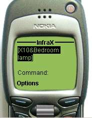
The background color of the two List Boxes (device and command) depend on the type of the selected device. For all infrared devices (excluding IR Dimmer) the background is cyan. For special purpose devices, including X10 the background is yellow. For the virtual device named "Recorded" the background is green. This can help the user to better understand the current operation mode. For all the special devices, the interface is always minimized and cannot be extended (with the exception of Application mode, where you can extend the window and use the Delete button if you want to delete one of the defined commands).
When a X10 device is selected, the name "X10" is used as a prefix for the device name and the DIM value scrollbar is available, as in the following picture:
Using the DIM scroll bar you can select a DIM/BRI level for the DIM/BRI commands, between 0 and 100%, if the selected X10 device supports that function (like LM12 lamp module).
<home>
The configuration file
The configuration file (irremote.cfg) is a text based file which can be edited using for example Notepad. Starting with the version 1.1a there is no need to manually edit the file anymore. All the operation can be done using only graphical interface.
Note: Use a simple text editor. Do not use Microsoft Word or any other document editor. Keep a copy of the original configuration file for the situation when you will not be able to start the program with the modified configuration file.
The configuration file contains 3 main sections (General, Protocol specific, End), as follows:
[General]
...
[DEVICE1_NAME]
...
[DEVICE2_NAME]
...
[DEVICE3_NAME]
...
...
[IR Dimmer]
...
[X10]
...
[End]
The [General] section:
[General]
COMPORT= 1
# The currently
selected COM port for the infrared interface.
PROTOCOL= 8
# The number of the current protocol as in the order from the file.
PROCDELAY= 5
# A constant dependent on the processor used. Because the delay routine is not so accurate for the delays lower than 1ms, this value must be tuned during the first signal recorded. The length of the received pulse (T) must be around 10-11 units. As an indication, this value is 5 for a PII @300MHz and 25 for an Athlon @1GHz.
ITYPE= 1
# This number define the type of the hardware interface used to receive and/or send commands. It can be 0 (DCD Standard), 1 (IRMouse), 2 (IRMan), 4 (FirM). If TxD based send interface is used, then 16 is added to that value.
CGIPATH= /cgi-bin/
# The string define the path where the CGI script is stored on the web server. By default, for Microsoft Internet Information Server, this path is /Scripts/
BEEPON= 1
# If 1, then each read and/or send operation is associated with a specific beep.
IRINENA= 1
# If the value is 1, then the infrared input plugin is enabled, if 0 then the infrared input device is disabled (or not monitored).
IROUTENA= 1
# If the value is 1, then the infrared output plugin is enabled, if 0 then the infrared output device is disabled (cannot send infrared commands). If both of infrared plugins are disabled, then the infrared devices are not displayed in the list.
X10COM= 0
# The currently selected COM port for the X10 interface (CM11/CM12). If the same port is used for both infrared and X10, then this value is 0.
X10ENA= 0
# If the value is 1, then the X10 output plugin is enabled, if 0 then the X10 device will not be displayed in the Listbox of the available devices .
IRDIMENA= 0
# If the value is 1, then the IR Dimmer output plugin is enabled, if 0 then IR Dimmer device will not be displayed in the list of the available devices.
APPLICATIONENA= 0
# If the value is 1, then the Application output plugin is enabled, if 0 then Application device will not be displayed in the list of the available devices.
WINAMPENA= 0
# If the value is 1, then the Winamp output plugin is enabled, if 0 then Winamp device will not be displayed in the list of the available devices.
WINAMPPATH= C:\Program Files\Winamp\
# This is the path where the Winamp application is installed and cannot be edited from the graphical interface. If you have installed Winamp in another location, then you must edit this line in the configuration file, manually.
BTCOM= 4
# The currently selected COM port for the Bluetooth serial port.
BTENA= 0
# If the value is 1, then the Bluetooth input plugin is enabled, if 0 then bluetooth device will not be displayed in the list of the available output devices in monitoring configuration window.
BTMODE= 0
# If the value is 0, then the Bluetooth mode is set to Auto, if 1 is set to Manual.
MONITOR= 0
# This is stored the monitoring status. When '1', the monitoring is activated and remains activated when the application is restarted.
The protocol specific section is explained based on Sony protocol
[TV]
GPROTO= 1
# The generic protocol is represented using a decimal value: 0 (NEC), 1(SONY), 2(RC5)
SENDPLS= 550
# The length of the sent data pulse (T), in us.
Usually, for most of the NEC/SONY protocols, this value is 550us.
REPEAT= 40
# The distance in multiple of T between two consecutive sequences of the signal. If it is 0, then the code sequence is transmitted only once.
BITG= 1111
# The format of the start bit in samples of T's.
BIT0= 01
# The format of the 0 bit in samples of T's.
BIT1= 011
# The format of the 1 bit in samples of T's.
GREPEAT= 40
# The distance
in multiple of T between two consecutive sequences of the signal (equal with
REPEAT) if the sync bit is repeated. If it is 0, then no sync bit is used (as in
RC5 protocol). If it is 1, then the sync is transmitted only with the first data
sequence.
#Sony TV-KV29X5
# This is the
device description, in clear text.
G001010010000,TV-MUTE
...
# This is the format of one learned command: the data bits and the name of the command, separated by ','.
[X10]
# X10 available devices definition
/X10/*b3,X-Mas tree light
/X10/*b9,Living Light
/X10/*m13,Device without case
# This is a partially read-only device used to command X10 devices represented by friendly names instead of X10 type addresses (House Code + Device Code). It cannot be deleted, but the defined X10 devices will be stored here, in the specified format
[Application]
#Application start/stop
@c:\windows\notepad.exe,Start Notepad
pskill notepad,Close Notepad
...
# This is a special device used to start and/or stop application on the PC. The syntax is similar with the other sections. The full path to the application is stored, including the parameters (if available), followed by a comma and then the command name. If the application path and name is started with a "@" character, then the application is opened using desktop interaction, if not the is opened in the background.
[Monitoring]
# Monitored infrared events
BT&YES,Winamp&PLAY
BT&LEFT,Winamp&PREV
BT&RIGHT,Winamp&NEXT
BT&*1,X10&Living Light&On
....
# This is a special section dedicated to the monitoring function. The syntax is: DEVICE&COMMAND for the monitored infrared event, then a comma followed by the DEVICE&COMMAND for the output event (can be any event, including infrared, X10, Winamp, Application, IR Dimmer).
[END]
#This is the end of the file marker.
<home>
The application is based on several plugins. All of them are available from the Plugins menu. The ones which are enabled have a check before the plugin name. You can toggle between enable and disable clicking on the respective name. Between the two horizontal lines external user defined plugins will be displayed in a future release. For the moment, Add Plugin and Remove Plugin are not implemented.
For two of the internal plugins, clicking on the name will open the configuration window for that plugin: X10 and Bluetooth.
When a specific plugin is not checked, then that plugin will not be available in the devices listbox (not even for Monitoring configuration window).
<home>
Infrared input plugin
System calibration procedure (for infrared operation only)
The recording routine takes aprox. one sample per 55us. For this reason, the standard routines using high resolution timers are not so accurate for such a small interval. In order to have a correct representation of the input signal, the system must be calibrated, to compensate the errors which can appear.
Starting with the version 1.3.x, the calibration procedure (PROCDELAY parameter) is fully automatic. From the File menu select AutoCalibrate.
The following window indicate that you must press a button on a remote (to have good results, a Sony remote is the best choice, but you can use NEC type remotes too (like JVC, etc.) or any other type with a command pulse of around 550us.
Note: DO NOT USE RC5 type remotes (like Philips and some Samsung/LG TV) because for that type of remotes the pulse is much longer and the calibration give wrong results.
Keep the remote button pressed till you will receive the following message in the status bar:
![]()
If you receive an error message, try to rerun the autocalibration function. The calibration must succeed on any PC starting with a minimum of a PII/266MHz. If the error message states that the system is too slow and the processor is faster that the one specified, then some other applications can disturb this process (or a miss configured system).
You can further fine tune the PROCDELAY parameter using the File > ProcDelay menu. This is only recommended for the advanced users. This can be done from the following window:

<home>
Selecting the infrared input interface
The standard interface (DCDStd) use an active low DCD signal. The IRMouse interface use an active high signal on the DCD pin. IRMan interface use an internal PIC to receive and decode infrared signals, then send a 6 byte code to the PC. FirM interface is basically a DCDStd type one, with added infrared zoning support. To select between the interfaces, use the IRHw menu. This setting is saved in the configuration file and displayed in the box (28).
You can let the application to automatically detect the infrared input interface, using the Auto Detect function from this menu. If the interface cannot be automatically detected, then an informative message will be displayed and the Unavailable generic interface is selected. At a later time, for example if you change the COM port, you can force auto detection function from the same menu.
<home>
Importing a configuration file
Use this procedure to import specific devices from an existing configuration file. This can be used to import learned devices from an old version of the application and/or from the devices library which will be available soon on my site. Then you will be able to use the application to send commands without the need of an input interface.
To import a device, click on the File>Import Device(s) from Config File.
A standard Windows Open File dialog box will be displayed.
You can select any compatible file, usually with the extension CFG. Clicking on Open, you will be prompted with the list of the available devices in that file or with an error message if the selected file is not a standard one.
You can check only the devices you want to import, including the [General] section. They are represented using the description, so you can easily choose the correct ones. After you finish the selection, click on Import. If you do not want to continue, click on Cancel.
You will be prompted to enter a short device name (this will be added in the available devices Listbox) for each imported device. If the device exist, then you will be able to choose between override and cancel operation.
At the end, the list of the imported devices will be displayed.
The newly imported device(s) are now available in the devices Listbox and ready to be used.
<home>
Exporting a configuration file
You can export (save) device configurations for further reference (or backup) using the File>Export Device(s) to Config File menu. You will be prompted with the list of the available devices in te current configuration file used.
As you can see, the [General] section is not displayed in this list. It will be saved by default, even if no other section is selected. You can select the devices you want to save and then click on Export.
A standard Windows File Save dialog box will be displayed. Enter a name for the file. It will be automatically changed to CFG extension if something else is used. Click Save.
A message box will inform you about the success of this operation.
Note: Please export to a file all the devices you have learn and then send them to me by mail. In that way you can help me develop a device library which can be used by the people who does not have an input interface.
<home>
How to receive and record the infrared signal
In order to receive a new command, you must first connect the hardware interface and calibrate the system. You do not need to select a specific protocol. The protocol of the received command is automatically detected by the software.
Click the "Record" button an then press a key on the infrared remote control till you will hear a short beep.
If no command is received for 5s, a low pitch beep signalize the end of the recording procedure.
You must press again the Record button.
The form of the received signal is displayed in the black box and all the parameters are placed in the specific boxes from the main window. The graph color depend on the record status. When an invalid signal is received, the graph color is red. When a valid one is received, the color is green.
See the main window description for details.
In the fields (16) and (17) you get the information regarding the length of the pulses and in (18) the received data with the bit length in (10). If the detected generic protocol is UNKnown, then try to re-record the signal. All the fields must be filled with the parameters.
If the command is known, then in box 19 the Device&Command is displayed.
<home>
How to analyze the received signal
If the data displayed in (18) have a sequence as 'Gxxxxxxx' and the protocol is multi sequence based (REPEAT >1), this means that the received code is error free and can be used to be stored in the configuration file. The background color of this field is green if the received command is validated and can be saved.
For single sequence protocols, in order to validate a command you need to record the signal for two times minimum. After the first press, the background of the filed is red and the command cannot be saved at this moment.
If after the second record the code is validated, the background goes green.
If it is still red, this means that the command is not yet validated and you must further record the command.
If after the record the background is still gray, this means that the received command exist in the configuration file and the device/command is displayed.
<home>
How to create a new device in the configuration file
Starting with the version 1.3.x, you can automatically build a new device.
First select as device Recorded (a virtual one). The protocol Listbox background goes to green.
Record a new command and check to be validated (background green and all the parameter boxes filled).
Click on File > New Device. The New device window is displayed.
The device parameters are automatically filled. You have to choose only a name and a description for the newly created device and click on Save. You can choose any name you want, but '[', ']', ',' and '#' characters are not allowed. The name cannot have more than 12 or less than 3 characters.
All the parameters are displayed for final confirmation:
If everything is ok, click on Yes. The newly created device will be selected in the main window Listbox, together with a generic command named EMPTY.
NOTE: For advanced users or special situations, you can edit the values as needed before clicking on Save. If any value is out of range, you will be notified by a small window. If no error message are displayed and the windows is closed, this means that the new protocol has been saved.
<home>
How to edit an existing device parameters
First you must select the device you want to edit using (20). Then click on File Menu and Edit Device. You will get again the Device Parameters window.
Here you can edit any parameter you want, including device name then click Save to write the new parameters in the configuration file.
<home>
How to delete an existing device
First you must select the device you want to delete using (20). The click on File Menu and Delete Device. You can delete any device you want except IR Dimmer, X10, Application, Winamp and Recorded, which are read only.
<home>
How to store a new command in the configuration file
When the newly recorded command is validated (the (18) field background is green), you can press Save button to store the new command. You cannot save the command if the (18) field background is red (command not yet validated) or gray (command exist in the configuration file). You will be asked for a name for the new command. You can choose any name you want, but '[', ']', ',' and '#' characters are not allowed. The name cannot have more than 12 or less than 3 characters.
If no error is displayed, the new command is added to the (1) Listbox.
<home>
How to delete a command from the configuration file
Using (20) and (1) select the protocol and the command you want to delete, then click on Delete button. A confirmation box will ask you if you really want to delete the command. You cannot delete generic commands EMPTY or Record.
<home>
How to send an infrared command
First you need to select the hardware interface used. If it is DTR based, you must uncheck TxD (8) checkbox. For TxD based interface check TxD. The setting is saved in the configuration file.
Next select the desired device/command and click on Send. You can minimize the window during send operation by clicking on (4).
If Beep checkbox is checked, 2 short beeps (different pitch) will confirm that the command was send successfully.
The graph color is blue for a send command.
<home>
Click on Plugins > X10 to enter the configuration menu for the X10 plugin.
If you check Disable X10 then the X10 plugin is disabled. More than that, the X10 device will not be listed in the available devices Listbox.
You can define as many X10 devices you want, in the limit of the available House Code / Device Code addresses. The list of the defined X10 devices is loaded in the Description Listbox. To define a new X10 device, select first the device address (HC+DC) and enter a short description in the Description field (which will be empty if there is no any device at that address defined). Click on Add/Modify. If the device exist, you will be prompted if you want to rename it.
You can delete any X10 device, at any time, selecting that device and then clicking on Delete. It will be automatically deleted from the list.
When you have finished the X10 configuration, click on OK. In that moment all the changes will be stored in the configuration file.
<home>
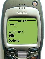
When the X10 device is selected, the main window is reduced to only the X10 functionality.
The available X10 commands in this version of the application are: All-Units-Off, All-Lights-On, On, Off, Dimm, Bright and All-Lights-Off.
Select the command and the friendly name of the X10 device and then click on Send.
If the command is DIM or BRI then you can select the dimming/bighting level between 0 and 100%. The default level is 50%. For any level over 40%, because of the way the CM11/CM12 interface works, the operation is done in 39% steps with a short break between them.
You cannot send BRI commands if the device is in OFF status. You must fist send ON command then DIM and then BRI. This is a limitation of the LM12 type Lamp Module, not of the application.
<home>
Resetting the CM11/CM12 type X10 interface
From time to time, the CM11/CM12 interface can go to a "Power failure" status when it send one time per second the 0xA5 hex char. When in this status, the application can return an error when tries to send an X10 command. You must Reset CM11/12 from the respective button in X10 plugin configuration window.
After this operation, the interface can be used again.
Note: This operation will RESET the clock in the CM11/CM12 interface and any defined X10 events stored in the interface memory. Use it on your own risk.
<home>
This plugin offer the possibility to start and/or stop an application as an output command. This can be very useful especially from the web interface, because you can start/stop applications from the web browser when you're not home, or when you want to trigger applications using an Bluetooth, infrared or any other future command (see monitoring function).
To define a new application type command, you must first select the Application device and then click on File > Add application.
You can then browse through the file system and choose the application you want to run and to include parameters too, if you want. The following files are accepted: executable(EXE, COM, BAT, CMD) and sound files (WAV, MP3). The sound files can then be played inside mplayer2.exe, only if this application is in the default directory (C:\Program Files\Windows Media Player).
You can build your own sound files (alarm, barking dog, etc.) and then use them as output events (from the web interface or in monitoring function).
The same virtual device can be used to stop or kill applications using freely available tools, like pskill.
<home>
The Bluetooth input plugin can be used with any Bluetooth enabled Ericsson phone, like: T39, T39m, R520, T68, T68i.
Before you can operate the BT plugin you must have a functional Bluetooth interface available on the PC/notebook. See the manual of the interface for details about configuration.
Check the driver configuration to see the number of the virtual COM port allocated for Serial Connection. Usually they are 2 ports: one for Local Services (like ActiveSync - connection initiated by the client) and the other for Client Applications (connection initiated by the PC). In the following picture there is an example for the TDK USB Bluetooth dongle.
You must note the COM port for Client Applications. This one will be used next to configure the BT plugin (here is COM4).
On the other side, be sure that the Bluetooth is activated at the phone level.
Do not forget to PAIR the PC and the phone in order to be able to communicate between then using Bluetooth. This is described in details in the phone manual.
Configuring Bluetooth interface
From the Plugins menu click on Bluetooth. The BT configuration window will be displayed.
Here you must select the COM port noted before. If you want, you can disable the Bluetooth plugin by checking the "Disable BT" checkbox. Select between Auto and Manual operation mode then click on OK.
You can define up to 10 separate output devices (from 0 to 9) which can be accessed by Bluetooth. For each of them you can define a friendly name which will be displayed on the phone display when that device is selected (see BT operation). After you enter the name, click on Change to save it in the configuration file.
See a later chapter for details about Manual and Auto operation mode.
Pressing any of the available keys on the phone will trigger an input event. In order to extend the number of available events, the '*' key is used as a SHIFT key.
Pressing '*' (as a SHIFT key) you can select currently device from the list of defined ones using the keys from 0 to 9. The friendly name of that device is displayed on the phone. Any key is pressed after that, will command the respective device, as defined in the Monitoring configuration.
NOTE: SHIFT key cannot be defined as an input event.
The lateral volume keys (UP and DOWN) are available too. More, for Ericsson T39 model, the flip status is available as an input event (FLIP OPEN and FLIP CLOSED).
Phone in/out of the Bluetooth range can be defined as input events too. You can use this for presence detection purposes.
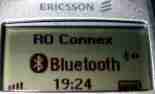
Bluetooth interface is initialized only during monitoring. After the initialization the phone display must look like:
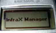
Starting from now, any key press is monitored by the application and can trigger an output event if defined.
The display returns to the normal status when monitoring is deactivated or when the Bluetooth radio link is lost. In this situation, the radio link is lost too.
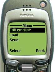
You can manually return to the normal status by clicking on SHIFT+'#"(keep '*' pressed and then click on '#'). A short message (3s) will be displaying to inform you that InfraX is deactivated. In that way, you keep the connection to the phone, as you can see from the following picture (the two small arrows in the left of the BT symbol).
To return to the InfraX mode operation, go to the Accessories menu (Extras > Accessories > InfraX Manager) and select it. You will be back to the InfraX Manager display.
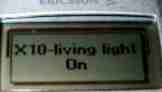
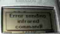
If you have defined monitored events with Bluetooth then any message displayed in the status bar will be displayed on the phone display too. Let's say, if you have defined BT events to control Winamp, you will get the song name displayed on the phone.

Here are some other examples for X10 and infrared. As you can see, the error messages are displayed on the phone display too.
Automatic vs. Manual operation mode
They are two type of operation modes for the Bluetooth plugin. Take into consideration that the BT connection is activated ONLY WHEN MONITORING IS STARTED.
In Automatic mode, even if you start the monitoring with the phone powered off, when the phone will be powered on and Bluetooth enabled, the InfraX application will automatically connect to the phone and initialize the InfraX Manager on the phone. When the BT remote is active, the IN field in the Monitoring window goes from yellow (default) to green. A BT input event named CONNECTED is triggered too. When the phone is powered off or goes outside the normal operation range and the radio link is lost, a DISCONNECTED event is triggered and the background goes back to yellow. You can define let's say an event that when you enter the PC room, the light turn ON or you receive an welcome message..:-)).
Later on, when you come back in the range or the phone is restarted, it automatically reconnects to the InfraX application, without any user intervention. The reconnection time is maximum 15s.
In Manual mode, the BT is initialized when monitoring is started only if the phone is available. If not, it will remain disconnected. In order to force reconnection, you must manually restart the monitoring function.
In this mode, the events CONNECTED and DISCONNECTED are not available. Use this mode only if you have problems using the automatic one.
<home>
The following Winamp commands are available:
POWER ON - starts the Winamp application with the currently selected playlist
POWER OFF - close Winamp
PLAY - play the current music file from the playlist
PREV - play the previous music file from the playlist
NEXT - play the next music file from the playlist
PAUSE - pause/resume the current song in playlist
STOP - stop playing
FFW - step forward in the current song
REW - step back in the current song
NEXT in PL - set playlist index and display the next song in PL (without changing the play status)
PREV in PL - set playlist index and display the previous song in PL (without changing the play status)
NEXT 10 in PL - set playlist index and display 10 songs further in PL (without changing the play status)
PREV 10 in PL - set playlist index and display 10 songs back in PL (without changing the play status)
VOLUP - volume UP by 10%
VOLDOWN - volume DOWN by 10%
GETNAME - get the name of the current song
EQON - toggle equalizer status
REPEAT - toggle repeat mode status
SHUFFLE - toggle shuffle mode status
PLAYLIST - open playlist
DOUBLE - toggle display in normal/double size
VISUAL
TIME ELAPSED - set Winamp display time in 'time elapsed'
TIME REMAINING - set Winamp display time in 'time remaining'
The song name is displayed in the main application status bar.
When a Bluetooth enabled GSM phone is used to send commands, then the song name and the command feedback is displayed on the phone display. The same for the WEB/WAP interface.
<home>
You can define the following mouse events as output events:
LEFT CLICK, RIGHT CLICK, DOUBLE CLICK, LEFT, LEFT UP, UP, RIGHT UP, RIGHT, RIGHT DOWN, DOWN, LEFT DOWN.
A nice application for this is to use the Bluetooth phone as a radio remote for your Powerpoint presentation.
<home>
The monitor function allows you to define input events (for the moment only Bluetooth and infrared) and an associated output event (of any available type, including infrared, X10, IR Dimmer, Application or Winamp). To define the monitored events, click on Monitoring > Configure.
A new window is displayed.
You can select the input device and command from the list boxes (IN Device and IN Command) to be monitored and any device/command from Out Device/Out Command to be executed when the monitored command is received. After that, click on Add to add this event to the list of monitored events in the Available monitored events list box. At any time, you can delete any monitored event from the list. In this version you cannot disable an event, just to delete it.
For the BT type input commands only (except "flip open", "flip closed", "connected" and "disconnected") a new listbox is displayed, containing the defined device list for BT phone. You can choose the specific device (selected on the phone with the SHIFT key) for that specific input command to be monitored.
When you have defined all the events you want, start the monitoring clicking on Monitoring > Start
You cannot start monitoring if there is no available input interface. From the infrared interfaces only DCD Standard and IRMouse are supported by the monitoring function. If everything is ok, the main window changes to a different one for all the monitoring period. The status is displayed in the status bar.
As you can see, in this case the received command is Bluetooth Connected, means that the Bluetooth phone is connected to the InfraX Manager. Connected event does not depend on the Bluetooth device selected, so here you see only BT for the input device.
When a defined command is received, it is displayed in the first yellow field as DEVICE&COMMAND. When the received command is defined in the monitored event list, the output command is executed and his name displayed in the second yellow field ,in the same format, like in the following picture:
If there is no event defined for the received command, the OUT field will display none. You can trigger several output events with a single input event. Just define several monitored events with the same input command. They will be executed one by one, in the list order. If more than one output command is defined for a single input event, all of them are displayed in the OUT field, separated by ';'
For Bluetooth input commands, the device is displayed BT0 to BT9, depend on the selected device (with the exception of the special commands: Connected, Disconnected, Flip Closed and Flip Open.
For Winamp output commands, the song name is displayed in the status bar after a symbol which represent the current operation: PLAY (>), PAUSE (II), NEXT (>>), PREV (<<)
<home>
Minimizing application and icon modes
When you minimize the main application, it will remain active in the taskbar, with a small icon. The color and form of the icon, describe the actual status of the application, as in the following examples:
![]() Monitoring is stopped;
Monitoring is stopped;
![]() Monitoring is started, but no active
Bluetooth phone is in range;
Monitoring is started, but no active
Bluetooth phone is in range;
![]() Monitoring is started and an active Bluetooth phone is in
range.
Monitoring is started and an active Bluetooth phone is in
range.
You can start/stop the monitoring, restore the full window, restart monitoring or exit application by right clicking on the taskbar icon and selecting the respective command from the available ones.
If you close the application when the monitoring function is started, at next startup the monitoring will be automatically activated.
<home>
The web interface can be used with the same irremote.cfg configuration file to send commands remotely, using a simple web browser. The provided functions are:
- load the available protocols from the configuration file;
- load the available command for the currently selected protocol from the configuration file;
- transmit the command using the web browser;
- display a confirmation message if the command has been sent successfully, or an error elsewhere, in the same web page;
The graphical interface is very simple, in order to take as little space as possible and to be integrated in an existing Web page, as a separate frame (for example).
The web functionality is based on a single CGI script named wim.cgi, which is copied by default in the same directory as the IRM application. It shares the same configuration file (irremote.cfg) and low level DLL (win32ser.dll) as the main application. The DLL is installed in the %SYSTEMROOT%\System32 directory, but the configuration file must be copied in the same directory as the CGI script file in order to operate.
<home>
The WAP interface is a CGI script too, but compatible with the WML format. In this way, it can be displayed on any available WAP browser, like: Pocket PC Internet Explorer (WAP support included), GSM and/or CDMA phones with included WAP browsers (the majority of the today GSM phones, even low ends). You can use your own mobile phone from everywhere in the world to command any home device and get a feedback about your command.
Just a couple of examples on how the page looks on different WAP devices:
a. A Pocket PC Internet Explorer on a Compaq iPaq H3870 device, connected to the internet using a Bluetooth enabled GSM phone (Ericsson T39):
b. An old Nokia 7110 GSM phone:
As you can see, you have the full functionality of the WEB interface from your phone. The exact way in which the page is displayed on a specific WAP phone depends on the phone model. The feedback is displayed too on the phone display.
<home>
How to install the web & WAP interfaces (server part)
For the moment the installation procedure for the CGI script is manual.
The files needed in order for web interface to work are:
wim.cgi - CGI script for Web (HTML) access including the remote functionality
wwim.cgi - CGI script for WAP (WML) access including the remote functionality
irremote.cfg - the configuration file (the same as for the main application)
win32ser.dll - the library with the hardware driver (the same as for the main application)
Both CGI scripts and the configuration (irremote.cfg) file must be copied in the usual Script directory of your web server (C:\InetPub\Scripts is the default for Microsoft Internet Information Server).
The directory can be any other, as you want, just not forget to permit running CGI scripts in that directory.
Now you can open the browser window, enter the address:
http://server.domain.com/Scripts/wim.cgi or
http://server.domain.com/cgi-bin/wim.cgi or any other, depend on the scripts directory used.
where server.domain.com is the fully qualified name of your web server.
You can use SSL connection (basic authentication over HTTPS) for more security on your web page.
If you need further details, mail me at dtoma@fx.ro
You can integrate this script in a separate frame in your own web page or application. The space occupied by the interface is very small.
In order to permit your web server (usually IIS) to serve WAP (WML) pages to the clients (WAP browsers), you need to go to Website Properties > HTTP Headers > MIME Map (File Types) and to add a new type as :
Associated extension: .wml
Content Type (MIME): text/vnd.wap.wml
This is all. You can now access your CGI script from a WAP browser too, using the address:
http://server.domain.com/Scripts/wwim.cgi or
http://server.domain.com/cgi-bin/wwim.cgi or any other, depend on the scripts directory used.
<home>
How to use the web & WAP interfaces to send commands
The graphical interface is very simple.
When you start the page specified before, select one of the devices from the list (ex. VCR1) and click on Load button, the window must look like this:
The full functionality of the main application (for send commands) is available in the web interface too.
The device and command list boxes are defaulted to the first protocol/command from the lists. Select desired protocol and click on Load to load the list of the available commands for the selected protocol.
When the desired command is selected, you simply click on send Send and the command will be sent on the remote machine.
A message will be displayed in the lower part of the window, indicating the status of the operation.
The windows background goes green for success, yellow for warnings and red for errors, like in the following example.
The selected parameters remain unchanged after clicking on Send.
<home>
From the Monitoring configuration window, click on Clean to delete orphaned event definitions.
The following events will be deleted from the configuration file:
- using inexistent input or output devices;
- using inexistent input or output commands.
When the operation is finished, a summary of the operation will be displayed, for example:
<home>
Program history
15-June-2003: Major update (v1.7.0 )
- you can now select up to 10 different devices from a Bluetooth enabled phone (with a 'SHIFT' key), using friendly names (more than 120 different commands from a single GSM phone keyboard!);
- you can now import and export X10 devices, applications definition and monitored events too;
- the application can be minimized in tray (still access to Start/Stop/Restart monitoring and Exit functions). Tray icon format and color depend on application status;
- play MP3 and WAV files inside application, as applications (useful for vocal feedback messages);
- mouse as output plugin (ex: use a Bluetooth enabled phone or an infrared remote to control a Powerpoint presentation);
- Housekeeping function - automatically delete orphaned events;
- new, optimized CGI scripts, now with both WEB and WAP support (2 different scripts), for secure remote access over the Internet. You can now control your home from everywhere in the world using a WAP enabled mobile phone;
- new Winamp commands... read next/prev melody in the playlist + read prev 10, next 10, without changing the play status ' YES to play the currently selected melody in the playlist;
- if monitoring started, then application started in minimized mode;
- a new, simplified infrared input interface (DCDStd type) is available in the "hardware" section.
08-April-2003: Major update
(v1.6.0 )
- Bluetooth GSM support (Ericsson T39, T39m, T68, T68i, R520 only) - tested on T39m only;
- display InfraX status on the phone display;
- all devices are now plugins and can be enabled or disabled independently;
- use the GSM phone as a bi-directional Winamp remote (the melody name displayed on the phone);
- presence detection using the GSM phone (as two separate input events: CONNECTED/DISCONNECTED);
- you can trigger several output events with a single input event;
- restart monitoring function;
23-Mars-2003: Major update
(v1.5.0 )
- monitoring function
included;
- output events can be selected based on defined input events;
- monitoring cannot be started if invalid interface;
- monitoring status stored when exit application. After restart, the monitoring status is kept (you can put the application in Startup folder;
- Winamp support for output commands;
- automatically start Winamp when press on any Winamp command;
- support for applications start/stop direct commands;
- you can launch applications with or without desktop interaction (for example when nobody logged on);
- X10 CM11/CM12 interface reset function (useful when the interface is in "power failure" status");
- no more auto detect interface when the program is started (manually force auto detect from the menu);
- the graph is displayed even for invalid received commands, in red color;
- Device & Command list boxes color - cyan (infrared), yellow (special devices);
- each X10 device is now separated in the devices list (no more different list box for X10 devices);
- do not accept '%' and '&' chars for commands and/or device names;
- a status bar is displayed in the lower part of the window, even in minimized form;
- all messages (informative and errors) are now displayed in the status bar;
- MSSTDFMT.DLL file is now included in the distribution package;
- color codes used for the graph: green=valid code received, red=invalid or unvalidated, cyan=modified graph, blue=send;
- distribution name changed from "irmstandalone" to "irm" (for both zip and executable).
03-Jan-2003: Major
update (v1.4.x )
- changing the name to Dante's InfraX Remote Manager because of the added
X10 support;
- adding X10 support to send commands, including DIM/BRI by percentage (0-100%) and including from the web interface;
- address X10 devices using friendly names, not device address;
- Protocol Menus changed to Device Menus;
- unicity of the command name checked now only for the current protocol;
- check the correlation between REPEAT and GREPEAT when a new device is build;
- configuration file import/export using friendly device description;
- the tooltip for the devices list contains now the device description from the config file;
- no more Template generic device in the config file;
- device name can now be edited;
- new device can now be created only from Recorded virtual device;
- REPEAT and GREPEAT parameters automatically detected from recorded command;
- plen0 and plen1 are now textboxes, not labels, in order to be able to browse through data;
- graph color depends on operation mode: red(record), blue(send), cyan (manual resampled);
- no more EMPTY as saved command when nothing saved yet;
- no more FIRM parameter in the configuration file, now it is considered as a different Rec interface;
- Univex IR Wall Light Dimmer control support (ON/OFF/DIM/BRI);
- automatically detect DCDStd/IRMouse/IRMan/FirM interface at startup and/or when requested.
03-Nov-2002 : Major update (v1.3.3x)
-
windows installer/uninstaller available
- web interface included in the package as a cgi script (wim.cgi), which can be used in you own web application, as a separate frame
- full support for all known generic infrared protocols ( NEC, SONY, RC5)
- FirM interface (Frank's infrared zoning device) support for both versions
- auto calibration for the PROCDELAY parameter
- auto calibration for pulse length (T)
- REPEAT and GREPEAT parameters automatically detected from recorded command
- the possibility to send a newly recorded command before save it
- Recorded as new virtual protocol/command used to send a command before save for test purpose and to automatically define a new protocol
- IRMouse support as infrared input interface (DCD inversed interface)
- check correlation between REPEAT and GREPEAT when a new protocol is build
- new DLL with improved precision timing
- ComList back color depend on port status
- BEEPON - new parameter in the configuration file - enable/disable sounds
- program exit if errors in the configuration file
- new command can be edited from the CodeStr Text Box before send
- a new parameter in the configuration file RC5TOG Boolean value - toggle bit for RC5 protocol
- COM port closed all the time if not used by a routine
- no more bincode Text Box
- description for the new or edited protocol is now available in GUI
- no more PULSE1MAX parameter
- no more PULSE0MIN and PULSE1MIN as protocol parameters
- change for all PULSEPOL parameter to GPROT
- auto detect and display the protocol, no more need to select the protocol before detecting the command
- PROCDELAY can now be modified from the graphical interface
- REPEAT contains now the number of Ts between sequences and/or G bits or 0 if no repeat
- change Binary protocol to Template Protocol
.. and a lot more ... try and see..
25-Sep-2002: Major update (v1.2a)
- ITYPE parameter in cfg file - 0(DTR),
1(TxD), 2(IrDA), saved at exit
- use TxD as output, software carrier (+new hardware
interface)
- do not check for the interface anymore. You can use any
hardware you want as the correct input/output pin is used
- the bug in COM list handling solved (I hope so)
- no more graphic plot during Send for compact window
- the edited code can be saved as a new command
- no more sequence number in display
- code length display for both send, receive and code edit
- display both protocol / command even is not in the current
protocol
- display the received command name even if not from the
current protocol
12-Sep-2002: Major update (v1.1a)
- no
more BITEND as protocol parameter
- no more PULSEMAX as protocol parameter
- create new protocol from the graphical interface
- edit a protocol from the graphical interface
- delete
a protocol from the graphical interface
- save a new command from the graphical interface
- delete a command from the graphical interface
- auto validate single sequence commands
-
practically there is no need anymore to manually edit the configuration file
- all the automatic procedures are protected against user errors (I
hope..:-))
16-Sep-2002: First public release of the Web interface for the remote control manager (version 1.0)
06-Sep-2002: First public release (v1.0a)
Bibliography
Infrared codes for consumer Audio/Visual Electronics - Gabriel Ricardo, Michael Vandegriend, Scott Medynski
A Remote Control Study - Bret Connell, Chris Craig, Dana Smith
WinLIRC Project - Jim Paris, Scott Baily
LIRC Project - Christoph Bartelmus
CM11/CM12 communication standard - X10 Web site
<home>
Copyright
This application is a freeware. You can distribute it freely if you keep the original file package, including all the copyright notice.
The source code is not included.
New versions of this application will be available at:
Please send any comments or bugs to:
Dan Toma ( dtoma@fx.ro )