Wi-Fi remote controlled HF Antenna/Transceiver 4 ports switch
Version 1.0
Dan - YO3GGX - yo3ggx@gmail.com
This device can be used to connect one of up to 4 HF transceivers to a single antenna or one of up to 4 antennas to a single HF Transceiver. When not powered or immediately after power up, PORT 1 (lower left) is automatically selected.
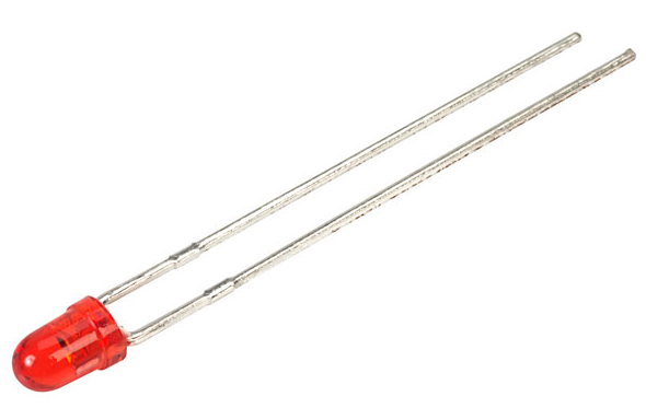
There is only one red LED that shows when the switch is powered up. There is no local control. Port selection is done through a Java application that can be run on any Windows, Linux, Mac or Raspberry Pi computer.
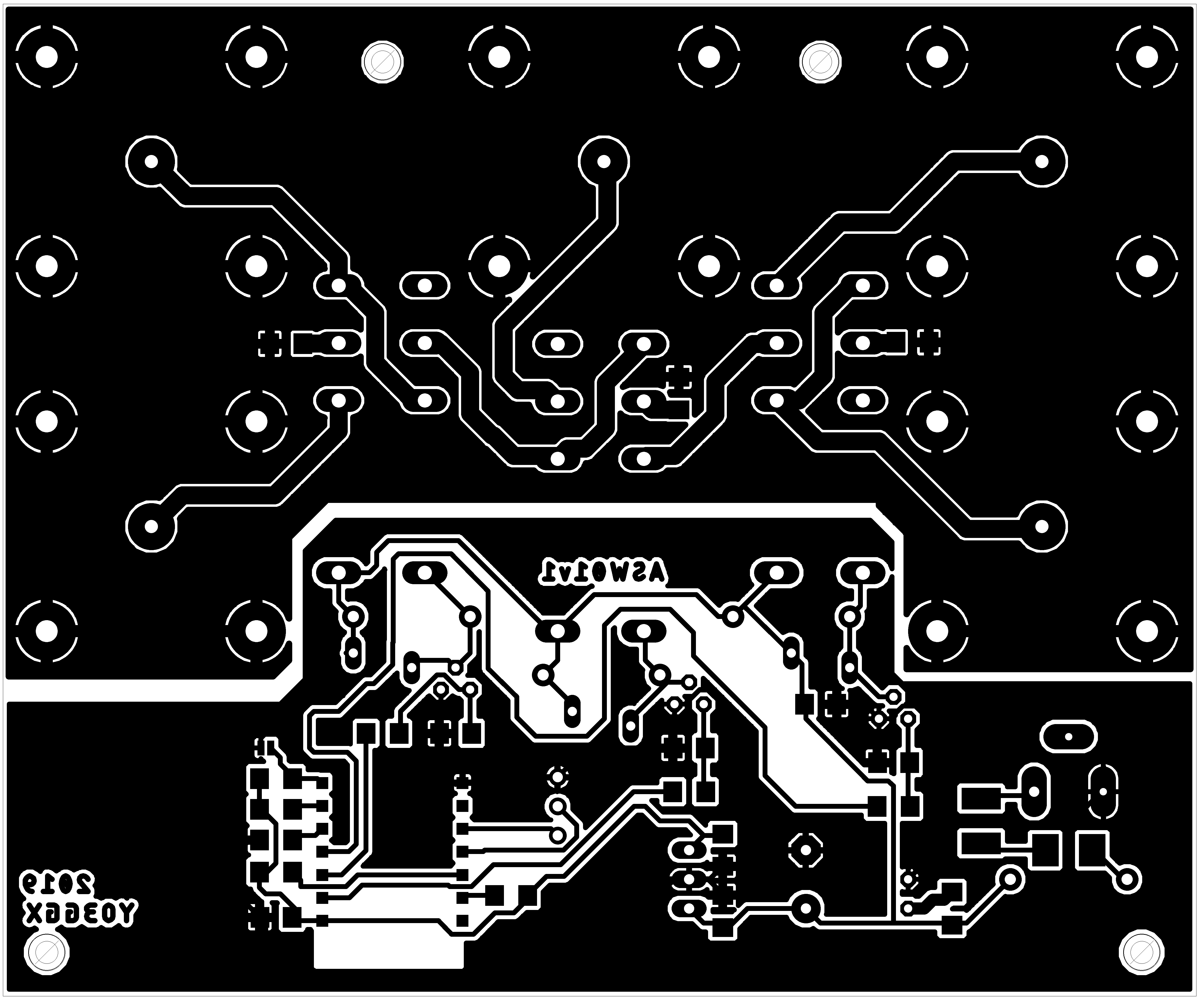
The PCB is single side, easy to be produced using toner transfer or any other preferred method. A 1:1 jpg file containing the PCB is provided. Eagle schematic and board files are available by request.
Both through hole and SMD components are used. The final products look like in the following picture.
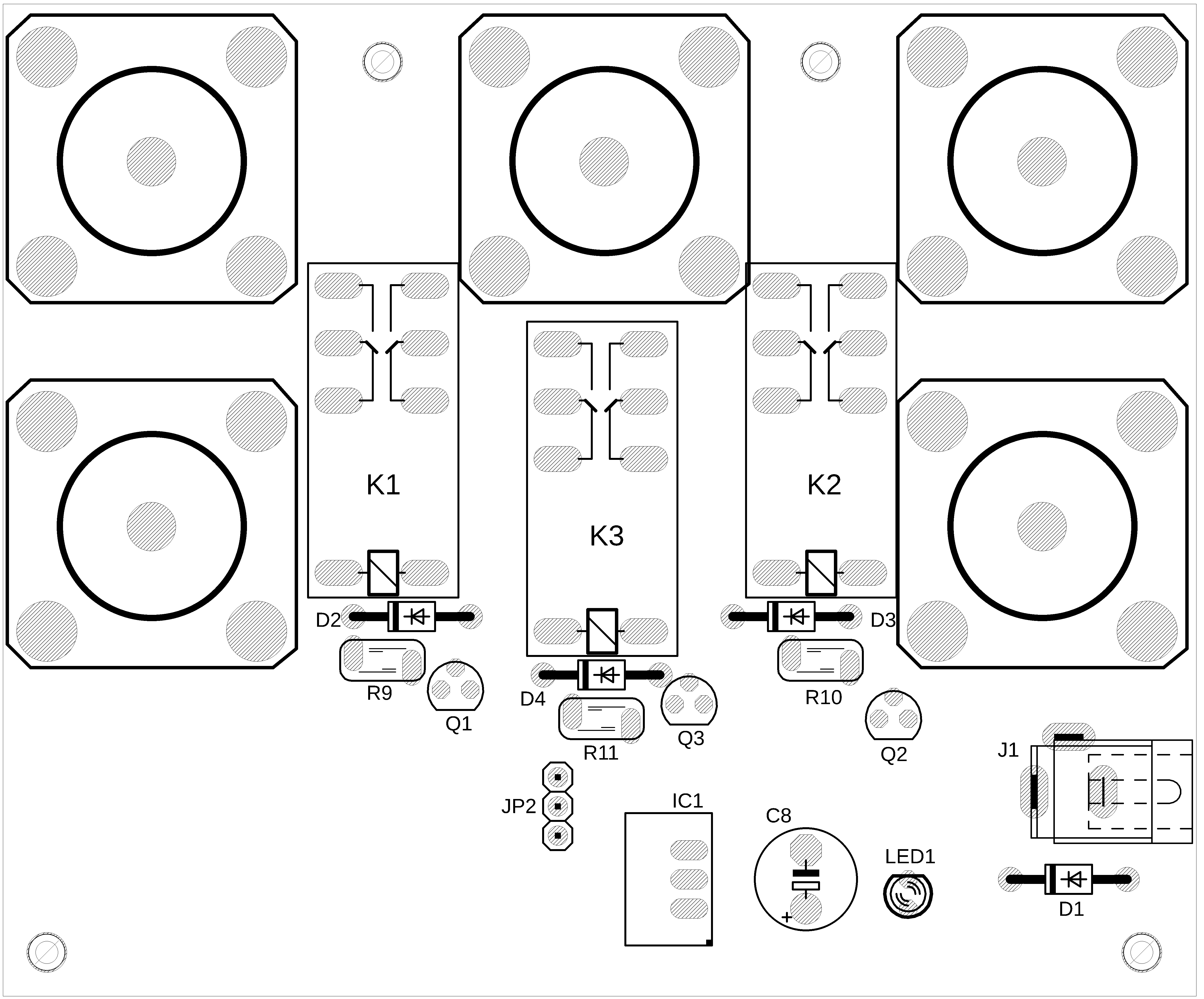
ASW01 switching for the 4 ports is based on 3 x DPDT relays (K1-K3), controlled by 3 low power transistors (Q1-Q3). Protection for overvoltage when switching is provided by 3 x varistors (R9-R11) and 3 x 1N4004 diodes (D2-D4).
L1 is used as a RF-choke. Protection if powered with reverse voltage is provided by D1. If something go wrong, the whole circuit is protected by a resettable 500mA fuse (F1).
In order to reduce the overall power consumption and the heat that can be generated by a linear voltage stabilizer (ex. LM 1117), I’ve decided to use a compact switching DC-DC converter (IC1). This can accept an input voltage of up to 28V and provide a stabilized 3.3V voltage required by the ESP module. The efficiency of this DC-DC converter is over 85% for the required output current ( < 200mA).
To control the 3 relays, GPIO 12-14 pins from ESP8266 are used.
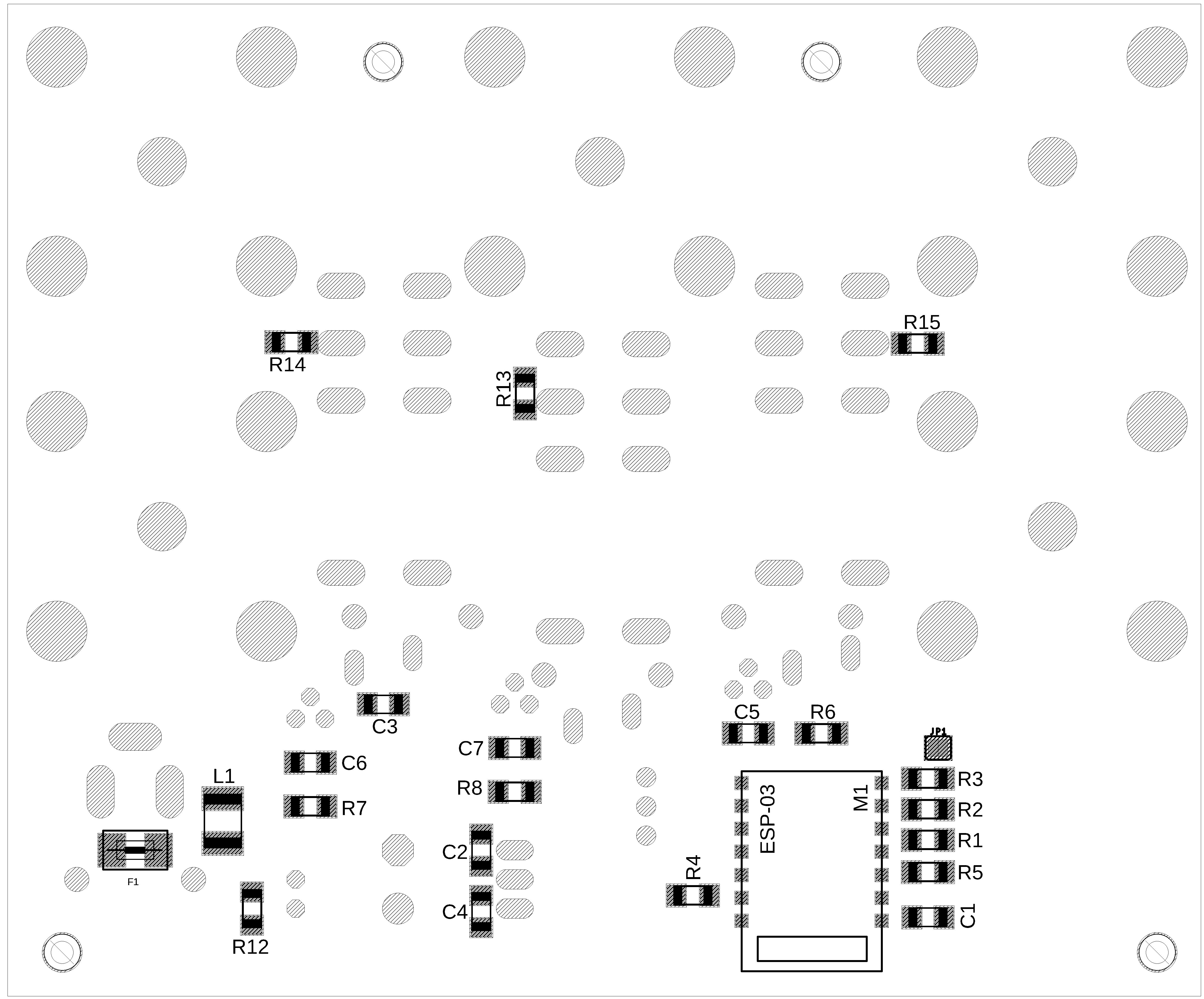
NOTE: Usually the following resistors are not required: R1-R4, as the ESP-03 module already contain the required pull-up or pull-down resistors. You can try to leave them unsoldered.
Resistors R13-R15 are in the current design replaced by solder jumpers. You can connect 3 x 50ohm/100W RF dummy loads through 3 pieces of RG316 coaxial cable. In this way, if you use the switch to select up to 4 transceivers to a single antenna, when the radio is not selected, a dummy load will be automatically connected to that radio.
This is the complete list of parts (BOM):
Part Qty Value Device Package
C1-C7 7 0.1uF/50V Ceramic SMD capacitor 1206
C8 1 100uF/25V Polarized capacitor E5-8.5
R6-R8 3 10K Resistor, SMD 1206
R1-R5 5 1K Resistor, SMD 1206
D1-D4 4 1N4004 Rectifier diode DO41-10
R12 1 2K2 Resistor, SMD 1206
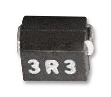
L1 1 MCNL453232-391K Inductor, 390uH, SMD 1812
R13-R15 3 0 ohm Solder jumper 1206
F1 1 MSMD050 PTC fuses, resettable, SMD 1812
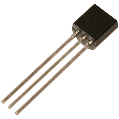
Q1-Q3 3 BC639 NPN Transistor SOT54D
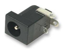
J1 1 DC, 2.1mm Jack – DC Plug
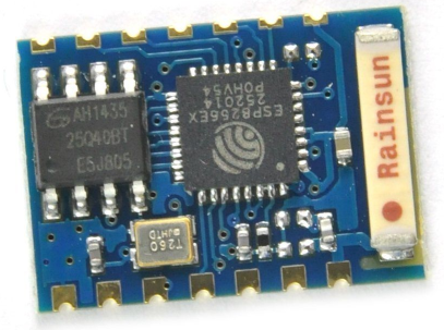
M1 1 ESP-03 ESP8266 module variant 03
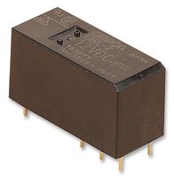
K1-K3 3 Relay DPDT Relay, Omron, G2RL-2
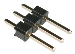
JP2 1 Header 3 pin Pin header, 3pin, 2.54mm
JP1 1 Jumper, SMT Jumper Solder jumper
IC1 1 R-78E3.3-0.5 Recom Switching regulator, 3.3V, 500mA
LED1 1 Red, 3mm LED, red, 3mm
R9-R11 3 SO7K25 Varistor, 25V
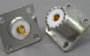
J2-J6 5 SO239 UHF connector, female, flange
Let’s now see where we can find the main components from a trusted source.
1N4004 - Rectifier Diode (~ 6c/pcs.) at:
https://ro.farnell.com/taiwan-semiconductor/1n4004/rectifier-single-400v-1a-do-204al/dp/2677320

MSMD050 - PPTC Resettable Auto Recovery Fuse 500mA (~ 30c/pcs.) at:
https://ro.farnell.com/littelfuse/2920l050dr/fuse-ptc-resettable-60v-500ma/dp/2368442
R-78E3.3-0.5 - Non Isolated POL DC/DC Converter, ITE, 1 Output, 1.65 W, 3.3 V, 500 mA, Fixed, Through Hole (~ $3) at:
https://ro.farnell.com/recom-power/r-78e3-3-0-5/dc-dc-converter-0-5a-3-3v-1-65w/dp/2218602
DC socket 2.1mm (~ $70c/pcs.) at:
https://www.conexelectronic.ro/ro/conectori-dc/4716-PRIZA-DC-2-1-MM-PANOU-PLASTIC.html
Pin header, 3pin, male, 2.54mm (~ 20c/pcs.) at:
SO239 panel connector with flange (~ $1.5/pcs.) at:
http://charma.ro/produs.php?id_produs=795
G2RL-2-CF 12DC - General Purpose Relay, G2RL Series, Power, Non Latching, DPDT, 12 VDC, 8 A (~ $2.5/pcs.) at:
https://ro.farnell.com/omron/g2rl-2-cf-12dc/relay-dpdt-240vac-30vdc-1-5a/dp/2065817
MCNL453232-391K - SMD, 390 µH, MCNL45 Series, 85 mA, 1812, Wirewound (~ 50c) at:
https://ro.farnell.com/multicomp/mcnl453232-391k/inductor-390uh-85ma-10/dp/1864352
LED, red, 3mm (~ 1c) at:
ESP8266 ESP-03 Serial WIFI Module Wireless Transceiver (~$2) at:
BC63916-D27Z - Bipolar (BJT) Single Transistor, NPN, BCE, 80 V, 100 MHz, 830 mW, 1 A (~40c) at:
https://ro.farnell.com/on-semiconductor/bc63916-d27z/transistor-bipol-npn-80v-to-226aa/dp/2453811RL
B72207S0250K101 - TVS Varistor, MOV, 25 V, 31 V, 77 V, Disc 7mm, Metal Oxide Varistor (MOV) (~30c) at:
https://ro.farnell.com/epcos/b72207s0250k101/varistor-1-6j-25vac/dp/1004370
![]()
The PCB (single side - bottom) is presented in the following picture.
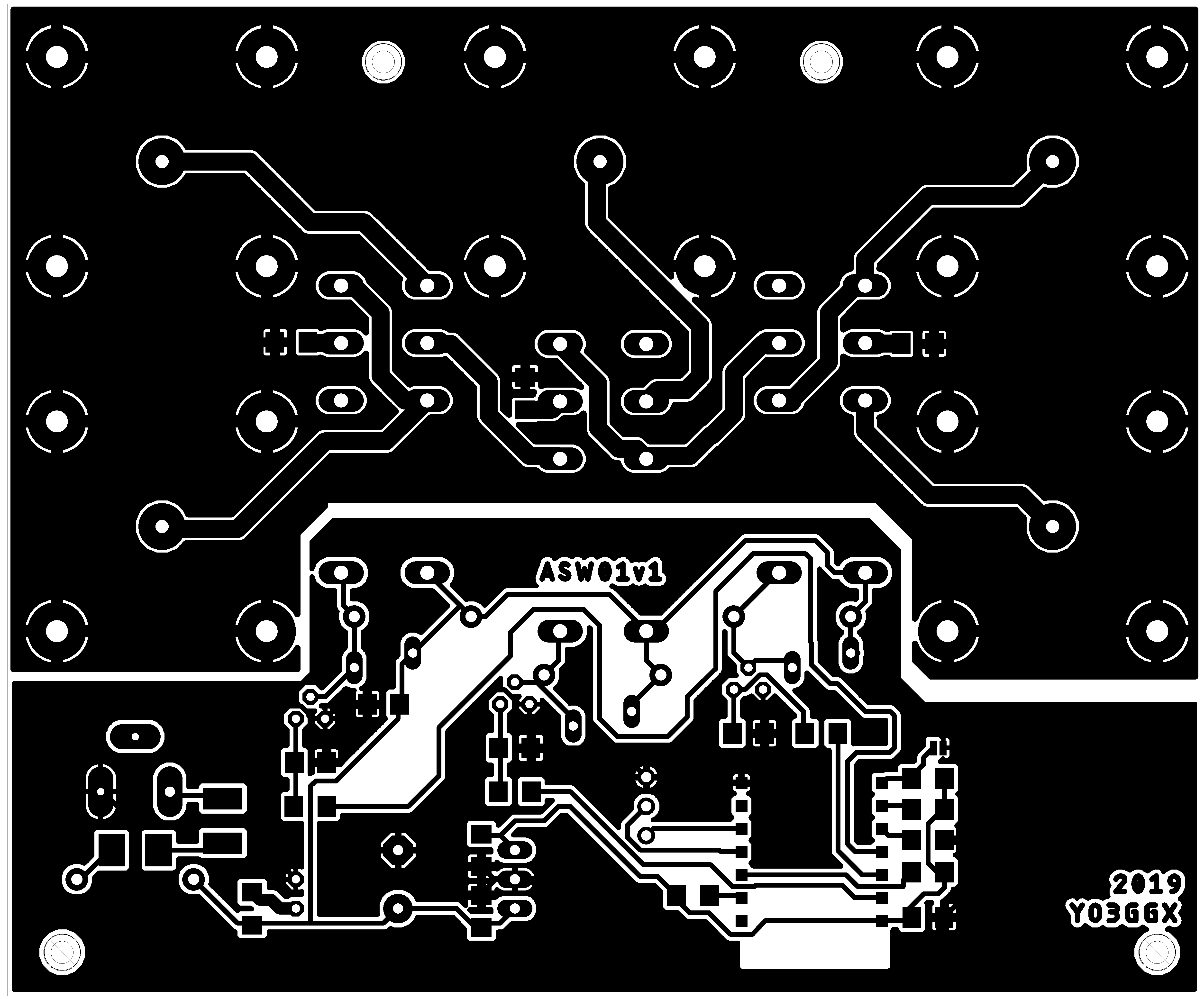
You can download the 1:1 (600dpi) mirrored PCB image from here:
https://www.yo3ggx.ro/asw01/asw01_pcb_bottom.png
This png file can be directly sent to a laser printer for the toner transfer procedure.
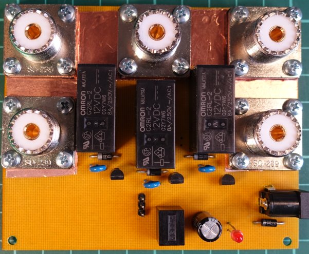
Through hole components are all mounted on the top of the PCB, according to the following picture.
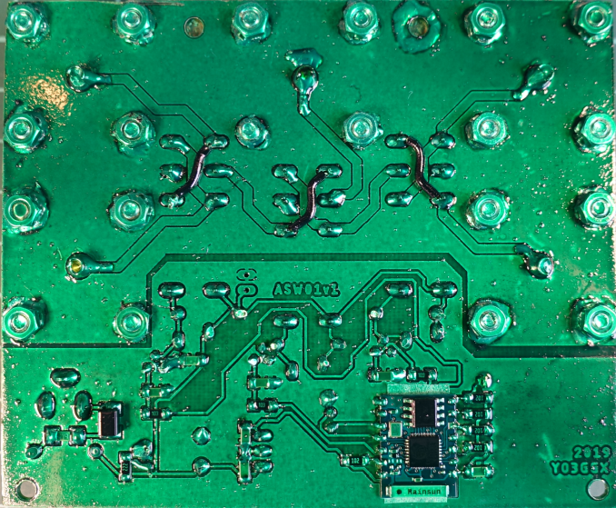
SMD components are all mounted on the bottom of the PCB, according to the following picture.
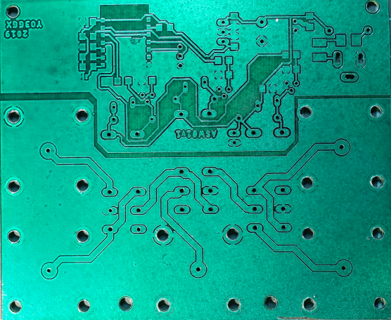
This is how my tinned and protected PCB looks like (without components):
The bottom of the PCB after all components were soldered looks like in the following picture.
The top of the PCB with all components mounted/soldered. The SO239 connectors are mounted using some 3d printed spacers, with M3x8 screws, M3 nuts and M3 washers.
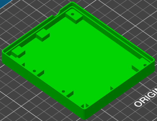
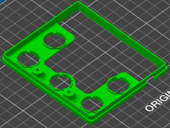
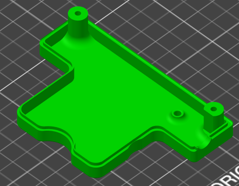
You can easily 3d print the case and the connectors spacers.
|
Case bottom |
|
|
Case top lower |
|
|
Case top upper |
|
|
|
|
|
SO239 spacers |
|
The STL files can be downloaded from here: https://www.yo3ggx.ro/asw01/case.zip
The case top lower and upper parts must be glued together. I’ve decided to split the top of the case in two in order not to use support.
The switch is mounted in the case using 4 nuts (inserted in the case bottom) and 4 M3x12 screws. The PCB is tight between the top and the bottom of the case.
For this project, the ESP module will be programmed using ESPEasy firmware. You can find more details about this firmware here: https://www.letscontrolit.com/wiki/index.php/ESPEasy
First power the Antenna Switch from an 8-14V power supply able to provide minimum 200mA. To program the Wi-Fi module, you will need an USB/Serial module, like for example this one:
NOTE: Take care to use an USB-Serial module that supports 3.3V devices connected to RxTx pins, otherwise there is a risk to destroy the ESP module.

Connect Rx, Tx and GND from the USB/Serial module to the 3-pin header (Rx-Rx, Tx-Tx, GND-GND). To flash the new firmware, follow the procedure described here:
https://www.letscontrolit.com/wiki/index.php?title=Tutorial_ESPEasy_Firmware_Upload
To put the module in programming mode, solder the jumper JP1 (on the back of the PCB). I recommend you to install firmware version R120.
NOTE: When choosing the flash variant, take into consideration that the ESP-03 module has a 512K memory.
After the flash has been successfully written, power off the switch and remove JP1 solder jumper.
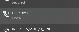
First time after the new firmware is installed (or after a factory reset – see later for more details), the module can be accessed only in ad-hoc mode (P2P). Go to your PC Wireless Network configuration and search for a SSID named ESP_XXXXXX. Connect to this AP using the password configesp.
As soon as the connection with the module is established, you must note the allocated IP address, let’s say 192.168.33.110. Power up the switch and then open your preferred browser and enter the address:
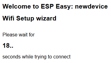
http://192.168.4.1 (this is always the IP address of the module when connected in ad-hoc mode). You must get the following window.
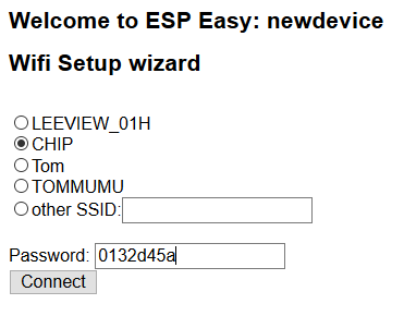
Select your local AP SSID, enter the WPA2 key in the Password field and then click on Connect button. Wait for ~20s for the module to connect to your AP.
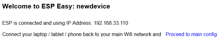
If connected successfully, you will see the IP address allocated to the module.
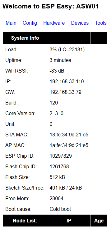
Now connect over WiFi or LAN to your local network and enter in the browser the IP address obtained in the previous step. The status page of your newly setup module is displayed
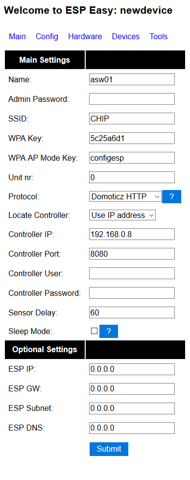
Click on Config. You can keep the default values and just rename the module asw01 and click on Submit button.
Click on Hardware link in the top of the page. In this project only the following pins are used, as output: GPIO12, GPIO13 and GPIO14. Set them to Output Low and leave the rest of the parameters unchanged. By doing this, the switch will always start on PORT1 when powered up.
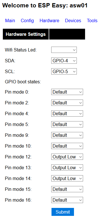
Click Submit. This is all you have to configure in the Wi-Fi module. You can now run the application to remotely control the switch over Wi-Fi.
To control the switch, I’ve developed a small Java application named ASW01. The application can be run on any Windows, Linux, Mac or Raspberry Pi computer. Currently only a GUI version of the application is available.
Download the application from the following location:
https://www.yo3ggx.ro/asw01/asw01.zip
NOTE: You need to have Java runtime 1.8_xxx installed on your computer in order to run this application.
Unzip the archive in a separate folder on your computer. You don’t have to install it. To run it, enter the following command from console, inside the folder where the jar file was unpacked.
java -jar asw01.jar
The main application window will open.
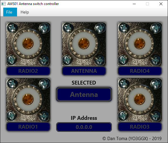
Double click on 0.0.0.0 IP address. You will be prompted to enter the IP address of the switch. Enter the address obtained during the ESP module configuration.
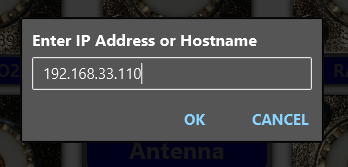
Click OK two times. As soon as the application connects to the switch, the IP address text will become white and PORT 1 will be automatically selected.

Double click on any of the 5 ports (PORT0 – PORT4, picture or text) to rename it according to your needs. You will be prompted to enter the new name.
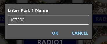
Do the same for all ports, including PORT0 (an End-fed antenna in this case).
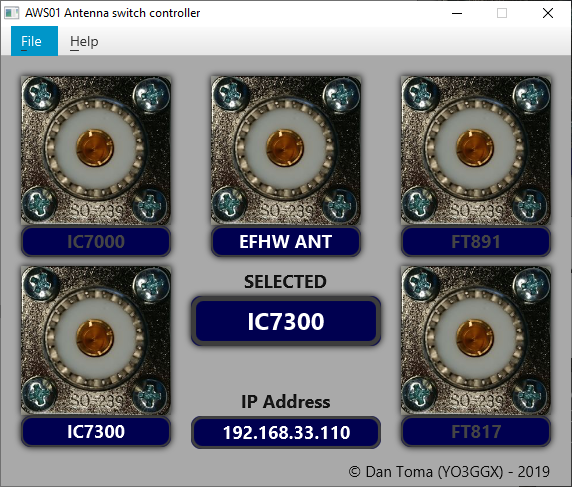
Now you can switch between transceivers or antennas by just clicking on the respective port. The radio name corresponding to that port will go white and the currently selected radio/antenna will be shown in the middle.
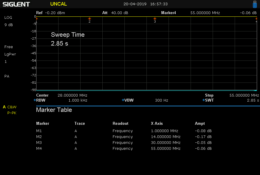
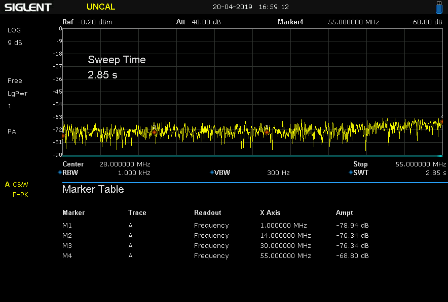
The following measurements were performed using a Siglent SSA3032X spectrum analyzer.
Attenuation is similar for all the ports in HF+6m bands:
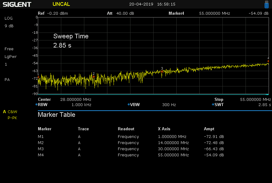
Attenuation on port 2 when port 1 is open and selected:
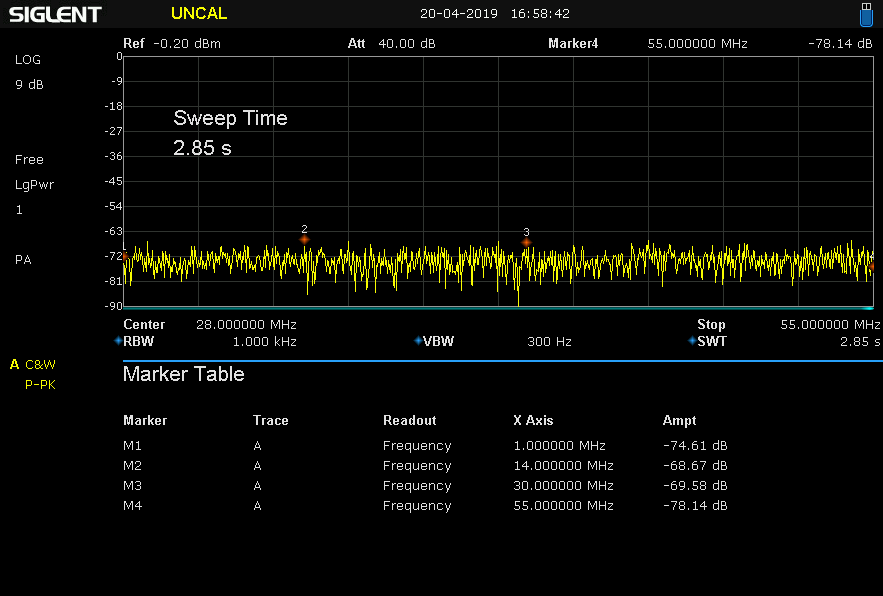
Attenuation on port 3 when port 1 is open and selected:
Attenuation on port 4 when port 1 is open and selected:
Attenuation on port 1 when port 4 is open and selected:
Attenuation on port 2 when port 4 is open and selected:

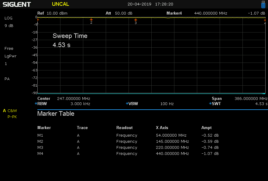
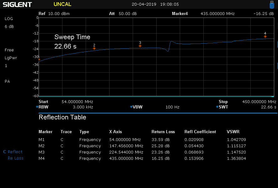
If you want to use this device as an antenna switch, then the parameters are acceptable even for 2m and 70cm bands. Here you can see some measurements for the frequencies between 54MHz and 450MHz.
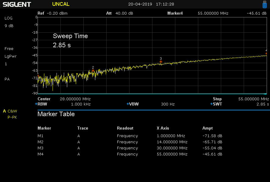
Attenuation for the selected port:
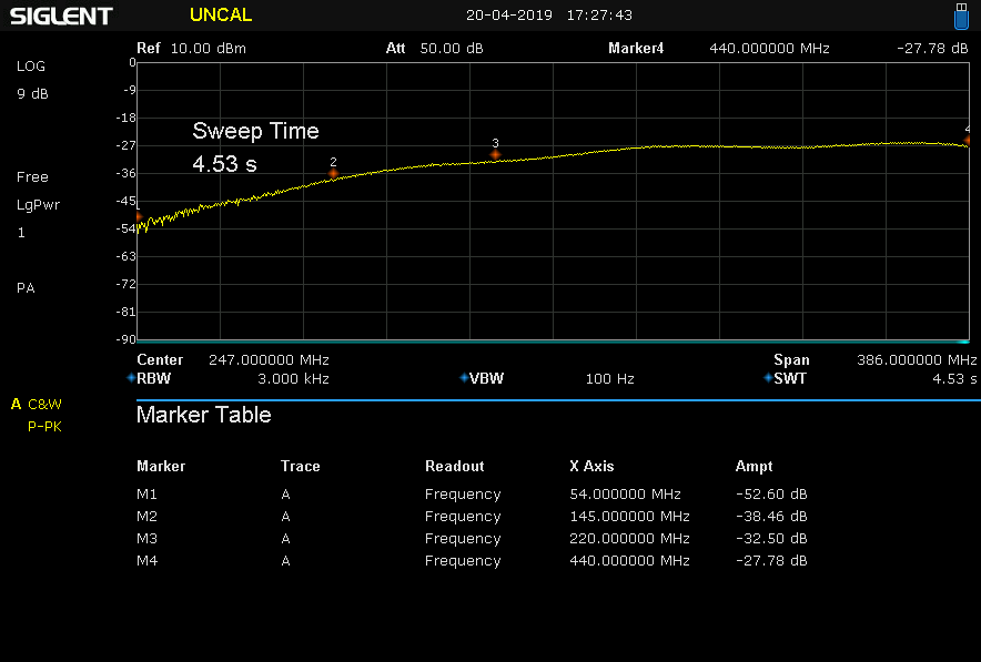
Attenuation on port 2 when port 1 is open and selected:
SWR when port 1 selected when terminated on a 50 ohm dummy load:
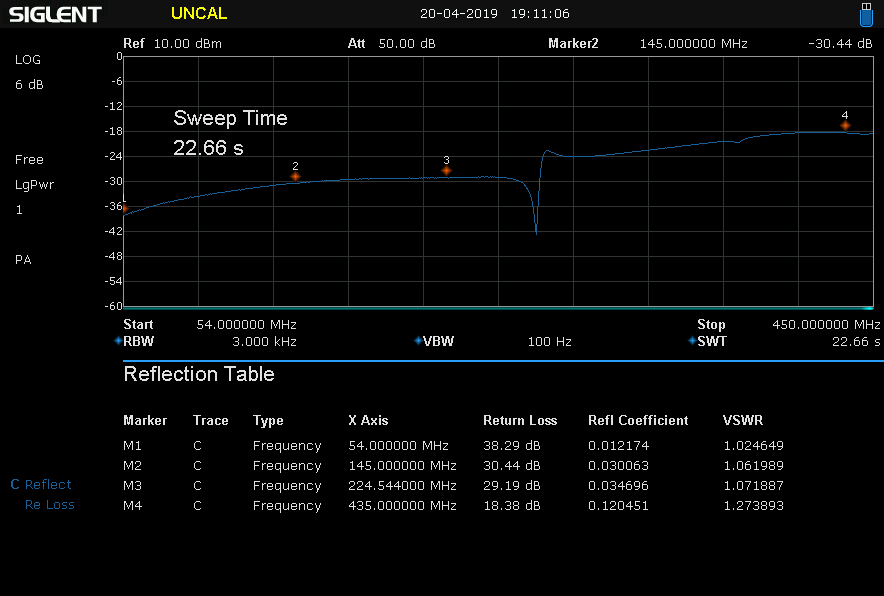
SWR when port 2 selected when terminated on a 50 ohm dummy load:
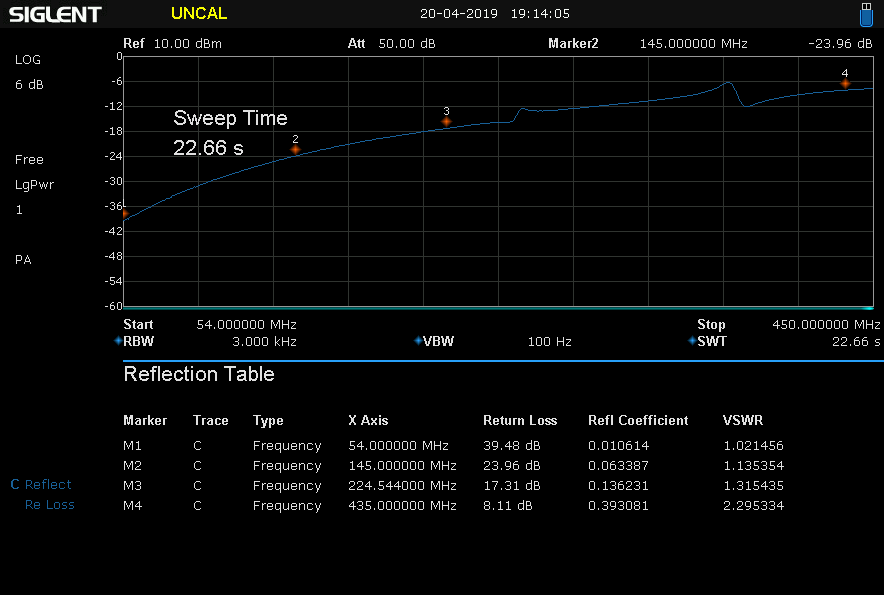
SWR when port 3 selected when terminated on a 50 ohm dummy load:

SWR when port 4 selected when terminated on a 50 ohm dummy load:
ESPEasy firmware: https://www.letscontrolit.com/wiki/index.php/ESPEasy
ESP-03 module: https://www.robotics.org.za/ESP-03
RECOM R-78E-0.5 datasheet: http://www.farnell.com/datasheets/2787645.pdf
Omron G2RL relay datasheet: http://www.farnell.com/datasheets/2191629.pdf
Initial version of the document (v1.0).
ASW_v1.0.pdf Bucharest, Apr 22th 2019 © Dan Toma – YO3GGX – yo3ggx@gmail.com